Reverse Osmosis Theory of Operation
How Does the Reverse Osmosis (RO) Process Work?
Water
Water exists in nature as a pure substance, but typically not in pure form. Many substances will readily combine with water. When water comes into contact with substances they either become dissolved solids, such as minerals, gases and organic compounds or they become suspended solids such as clay, silt, and microorganisms.
Dissolved Solids
Mixtures containing dissolved solids are commonly called solutions. Solutions form when a solute material, such as salt (sodium chloride), becomes dissolved in a solvent, such as water. When a particle of salt contacts water, the salt dissolves and spreads throughout the water until the salt as a solid no longer exists. The salt ions are still present, but they now exist in a liquid phase as part of the solution and are now referred to as dissolved ions. These ions carry either a positive or negative electrical charge, and will hereby be referred to as cations, if they carry a positive charge and anions if they carry a negative charge. Organics such as sugar & starch, will also dissolved and form solutions that typically will not ionize.
Suspended Solids
Suspended solids are materials that do not dissolve in a solvent (like water), exist as unevenly distributed particles in a mixture. Suspended solids larger than five microns are filtered out before the Reverse Osmosis Membrane Elements by way of pre-filtration.
Dissolved Ionic Content and Water Quality
The presence of ionic material (dissolved solids) in a solution, increases the solutions conductivity, or the ability to conduct electricity. Consequently, the use of a conductivity measurement testing device may be used as a means to approximate the number of dissolved solids in water. The higher the conductivity, the higher the dissolved solids content. The presence of dissolved and suspended solids may be detrimental to many water applications such as the production of steam for power generation or ingredient water used in the preparation of food and pharmaceutical materials. These dissolved and suspended solids must be removed or reduced from the water prior to use in these and many other applications. One effective method of removing the majority of these contaminants is referred to as Reverse Osmosis (RO)
Osmosis
Osmosis is a natural phenomenon that occurs when two solutions with different concentrations of dissolved solids are separated by a semi-permeable membrane. In natural osmosis, the solvent or water in this application travels through the membrane from the solution with the lower concentration of ionic materials to the solution with the higher ionic concentration. This process continues until the ionic concentration of both solutions is equal or until the resultant passage of the water through the membrane reaches the osmotic pressure of the solution if the solutions are trapped in a container as illustrated in Figure 1.
Figure 1

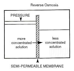
Reverse Osmosis
Reverse Osmosis is the reversal of this natural phenomenon, by the application of external pressure on the solution that contains the higher concentration of dissolved ions, this forces water through the semi-permeable membrane in the opposite direction, leaving behind the dissolved ions and the suspended solids. This is illustrated in Figure 2. In the reverse osmosis process, the water that passes through the membrane is commonly referred to as permeate, or product water, the water that remains behind the membrane along with the dissolved and suspended solids is referred to as the concentrate, brine or reject water.
Figure 2
The table below gives some approximate osmotic pressure values as an example of how much pressure must be applied to the solution with a greater ionic concentration before any water will pass through a membrane into a solution containing a lesser ionic concentration.
Table 1: Osmotic Pressure
| Salts | Concentration % | Approximate Osmotic Pressure PSIG |
| Sodium Chloride | 0.5 1.0 3.5 |
55 125 410 |
| Sodium Sulfate | 2 5 10 |
110 304 568 |
| Calcium Chloride | 1 3.5 |
90 308 |
| Copper Sulfate | 2 5 10 |
57 115 231 |
It is impractical to convert all of the water processed to product water for several reasons including the osmotic pressure which develops as a result of the concentration of the dissolved ions which accumulate on the one side of the membrane, and the inability to keep the membrane free from suspended solids that would foul the surface of the membrane if not removed.
The rate of product water passage or productivity through the membrane is referred to as the flux rate and is generally expressed in “gallons per square foot of membrane surface per day” or in “gallons per day per reverse osmosis membrane.” The flux rate of a particular membrane is generally limited by several factors including, temperature, operating pressure, and the requirement of surface flushing action to keep the membrane surface clean of suspended solids. Typically higher flux rates cause higher fouling rates.
The rate of recovery of feed water converted into product water is generally expressed in the form of a percentage, with the ratio of product water being expressed as the recovery rate. For example, if the feed flow rate of the RO unit is 100 gpm and the product rate from the RO is 75 gpm, the rate of recovery would be 75%. The remaining 25 gpm not passed through the membrane, or the concentrate water would be discarded and not recovered.
Reverse Osmosis Membrane rejection is an expression of the ability to restrict the passage of dissolved ions through the membrane and is generally expressed as a percentage. Feed water to the membrane contains 100 ppm of dissolved solids and the resulting product water contains only 2 ppm of dissolved solids after processing the resultant dissolved ions rejection rate is 98%. The opposite of this expression is also some-times used and is known as salt passage rate, which for our example would equal a salt passage rate which for our example would equal a salt passage rate of 2%. A membrane rejection rate of 100% is not practical due to imperfections in the membrane and the construction of the membrane element.
Practical Applications
Reverse Osmosis becomes practical for water treatment when synthetic, semi-permeable membrane material is packaged in a suitable membrane element. Typically the membrane elements are constructed of one of two classifications of membrane material including cellulose acetate or triacetate, or some type of plastic-based material such as a polyamide or polysulfone – based material. These materials are then arranged into one of four element configurations including flat plate, tubular, hollow fiber, or spiral wound, with the latter two configurations being the most common in today’s technology. Selection of the membrane material and element configuration is based on a number of factors including water chemistry, space limitations, product water quality requirements, and system pre-treatment design. The spiral wound element configuration in Figure 3 will be described, based on the design of the RO unit covered in this manual.
The spiral wound membrane element material configuration is constructed from a flat sheet membrane that is first folded and sealed to form an envelope, with one opened end. Porous backing material, placed inside the envelope separates the membrane sheets and forms a flow channel between them. The opened end of the envelope is then attached and sealed around a plastic permeate tube that is perforated, which allows the product water or permeate to pass into the product tube as illustrated in Figure 3.
Figure 3
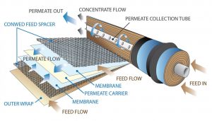
For compactness, the envelope of membrane material in then wrapped around the permeate tube in a spiral wound fashion with a coarse plastic screen referred to as a brine channel screen, being included in the wrap. This creates a flow channel between the surfaces of the membrane where the feed water enters the element and then concentrate or brine flow passes out of the element, as shown in Figure 3. The element is then covered with an outer wrap of semi-rigid fiberglass for protection and to assist in maintaining a uniform round shape. The final dimensions of the element are usually approximately 40 inches long by either 4” or 8” in diameter.
The elements are then put into one or more cylinder membrane element housings, which can contain one to seven membrane elements depending on the unit design. Once the membrane elements are housed in a membrane element housing, the assembly is generally referred to as a module. See Figure 4.
Figure 4
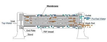
Pressurized feed water is introduced into one end of the module or membrane element housing. Some of the water driven by the feed pressure through the RO pressure vessel feed port and permeates through the membrane and passes into the product tube and exits the membrane element housing from the element housing product port as product water, less most of the dissolved solids and all of the suspended solids. The remainder of the water passes along the surface of the membrane with the concentrated dissolved and suspended solids and passes out of the element housing as concentrate, brine or reject flow from the membrane element concentrate port. The concentrated water is divided into recycle and concentrate streams. The recycle portion mixes with the feed water by returning to the inlet piping, allowing higher machine permeate recovery.
The membrane element housing or modules are generally arranged in stages when more product water is desired than one module can produce. The staging of the modules is designed to optimize the water flow patterns across the surface of the membranes. This uniform water flow promotes good flushing velocity across the membrane surface to prevent the accumulation of suspended solids on the surface, which would then foul the membrane element and reduce the productivity.
A simple example of an array would be a unit containing three modules, with two modules plumbed in parallel in the first stage and the third module plumbed in series after the first two modules in the second stage. In this case the feed water to the unit is first split into two streams with each half being directed into one of the first stage modules. On entering these two modules, some product water is produced from each side of the membrane element in common product water piping. That water that is not permeated through the membrane is passed out of the modules as concentrate along with the dissolved and suspended solids left behind. This water is then collected into a common first-stage concentrate header or reject header and directed to the feed of the third module which is plumbed in series behind the first two modules, where the process is again repeated. The second stage product or permeate is added to the first stage product and the second stage concentrate or reject flow is directed through a control valve then disposed of along with most of the dissolved and suspended solids.
Figure 5

Recovery Limitations
As previously described, product recovery is that ratio of water volume recovered as product water compared to the volume of water supplied to the RO unit as feed water. Naturally, in an ideal situation you would like to recover all of the water, but this is not practical for several reasons as described below.
If all of the water that was processed were converted to product water, there would be no water available to flush the membrane surface area free of remaining suspended solids. Consequently, the suspended solids would build up on the surface of the membrane and gradually restrict the flow of product water until no permeate or product water could be produced.
The presence of some dissolved solids such as silica, barium, strontium, or calcium and magnesium when present with carbonate or sulfate ions restricts the recovery of an RO unit more than other dissolved solids, due to their limited solubility in water. For example the presence of silica SiO2 in the feed water is oftentimes the limiting factor in RO Recovery, because it starts to precipitate out of solution when it reaches a concentration of 100-120 ppm. That means that if the feed water contains 30 PPM SiO2 then the recovery of product water is limited to about 75% because the SiO2 concentration will be concentrated by 4 times which will result in a silica concentration in RO reject of approximately 120 ppm, which is the limit of its solubility. If you tried to recover 80% of the water, the concentration of SiO2 would reach five times the feed water concentration of approximately 150 PPM and start to precipitate, fouling the membrane surface. The evolution of new anti-scalants and cleaners are helping to extend some of these recovery levels.