Veolia E4H Series Water Purification Machine User Manual
Veolia E4H Series Water Purification Machine User Manual
Buy Now
16,000 GPD – 43,200 GPD
60.6 m3/day – 163.5 m3/day
Download PDF
Table of Contents
1. Description
1.1 Definitions
1.1.1 Permeate rate (product water rate) [Qp]
1.1.2 Concentrate rate (reject rate) [Qc]
1.1.3 Feed rate [Qf ]
1.1.4 Reverse osmosis (RO)
1.1.5 Membrane elements
1.1.6 CIP
1.1.7 Average pressure [PAVG]
1.1.8 Concentration
1.1.9 Salt (Ionic) passage
1.1.10 Recovery
1.1.11 Salt (ionic) rejection
1.2 Flow description
1.3 Machine nomenclature
1.4 Economy (ECN) model and deluxe (DLX) model options
1.4.1 ECN model
1.4.2 DLX model
1.5 Specifications for E-Series machines
1.5.1 Feed water specifications
1.5.2 Permeate flow rate
1.5.3 Concentrate flow rate
1.5.4 Operating final pressure
1.5.5 Pump
1.5.6 RO membrane rejection
2. Installation
2.1 Mounting
2.2 Piping
2.3 Electrical
2.3.1 ECN electrical system
2.3.2 DLX electrical system
3. Preparation
3.1 Pretreatment for water purification
3.2 Start-up
4. Operation and maintenance
4.1 Daily log sheets
4.2 Pre-filter
4.3 Flushing
4.4 Cleaning
4.4.1 Cleaning procedure for DLX and ECN models
4.5 Draining machine for storage/shipment
4.6 Membrane installation
4.7 Membrane replacement
5. Optional accessories
5.1 Standard options
5.2 External controls
5.3 Filters and water softeners
5.4 Storage tanks
6. Troubleshooting
7. Spare parts list
8. Return goods authorization (RGA) procedure
9. Warranty/guarantee
9.1 Machine warranty/guarantee
9.2 Desal* membrane element workmanship warranty
10. Operating logs
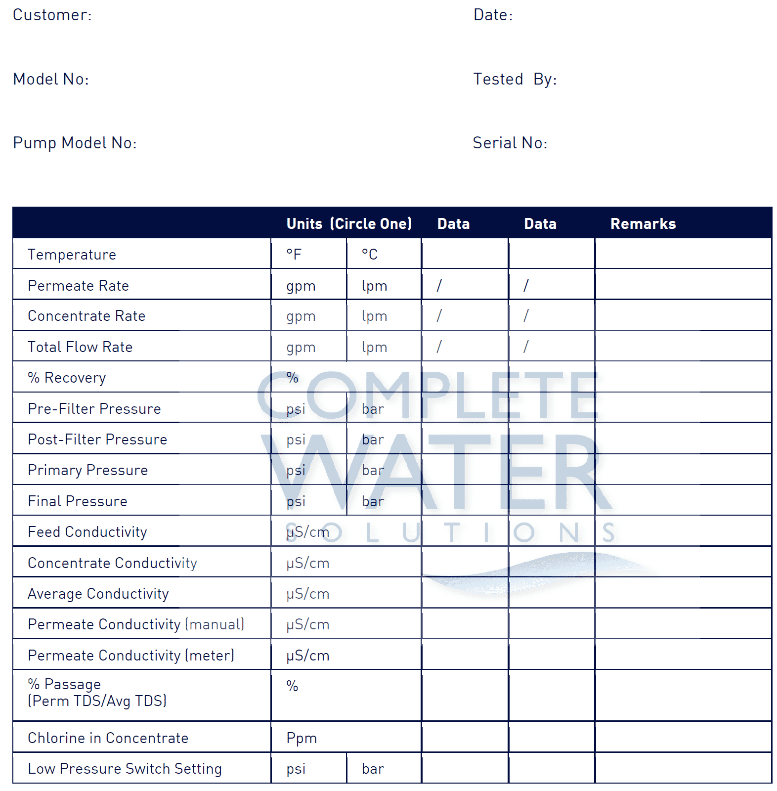
10.1 Start-up data
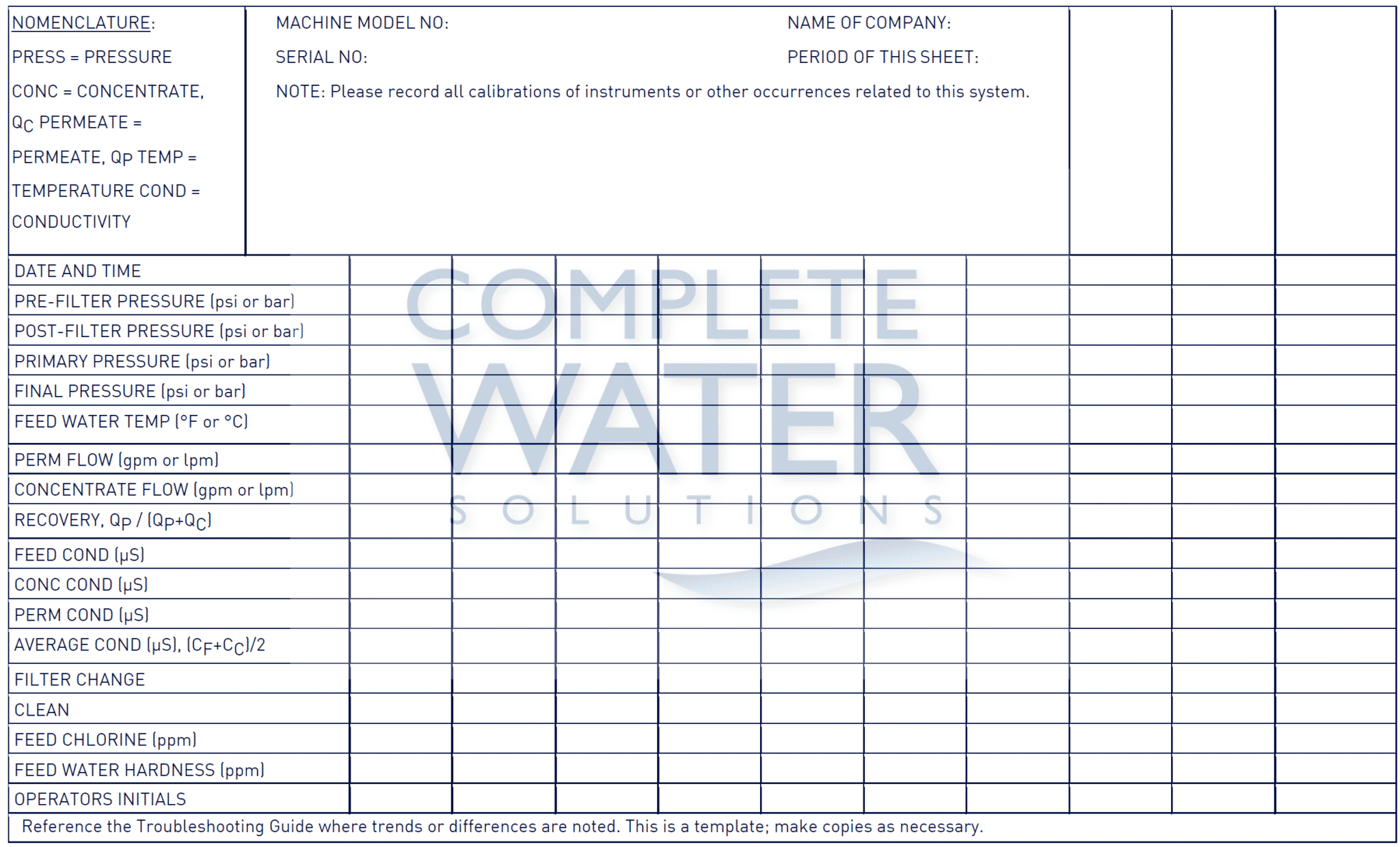
10.2 Daily log for Veolia Water & Process Technologies membrane machines
List of Tables
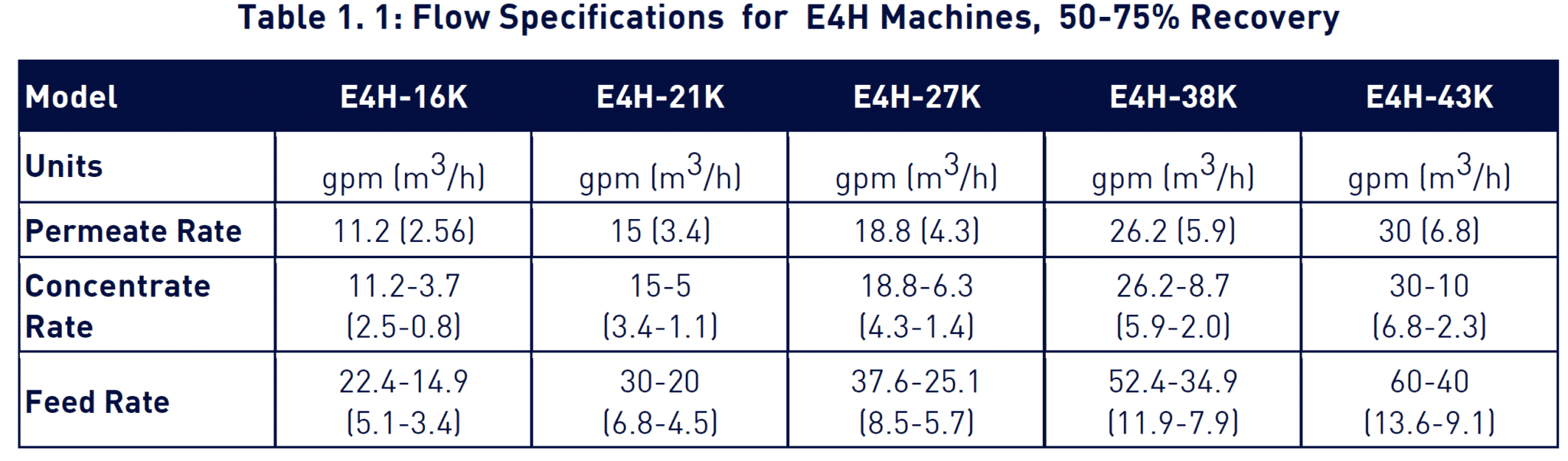
Table 1. 1: Flow Specifications for E4H Machines, 50-75% Recovery
Table 1. 2: Feed Water Requirements
Table 1. 3: Membrane Element Specifications – AG4040F*
Table 2. 1: Connection Schedule
Table 6. 1: Troubleshooting Guide
List of Figures
Figure1. 1: Normal vs. Crossflow Filtration
Figure1. 2: Membrane Element with Interconnectors
Figure1. 3: Cross-Sectional View of Membrane Element
Figure1. 4: Principle of Operation
1. Description
Your E-Series reverse osmosis (RO) machine is a durable piece of equipment which, with proper care, will last for many years. These instructions give operation and maintenance details vital to the sustained performance of the machine. Please read this manual completely before operating your machine.
1.1 Definitions
The operating definitions provided below will help you further understand your machine and this manual.
1.1.1 Permeate Rate (product water rate) [Qp]
The flow rate of purified water, which has passed through the membrane and out of the membrane element , expressed in gal/min (gpm) or gal/hr (gph) or liter/min (lpm) or cubic meters/hour (m3/h). Specified permeate rates are based on a feed water temperature of 77 °F (25°C). Permeate rate will vary with temperature.
1.1.2 concentrate rate (reject rate) [Qc]
The flow rate of water containing rejected solids to drain in gpm or gph (lpm or m3/h).
1.1.3 feed rate [Qf ]
The flow rate of incoming water in gpm or gph (lpm or m3/h). Feed water rate equals permeate rate plus concentrate rate.
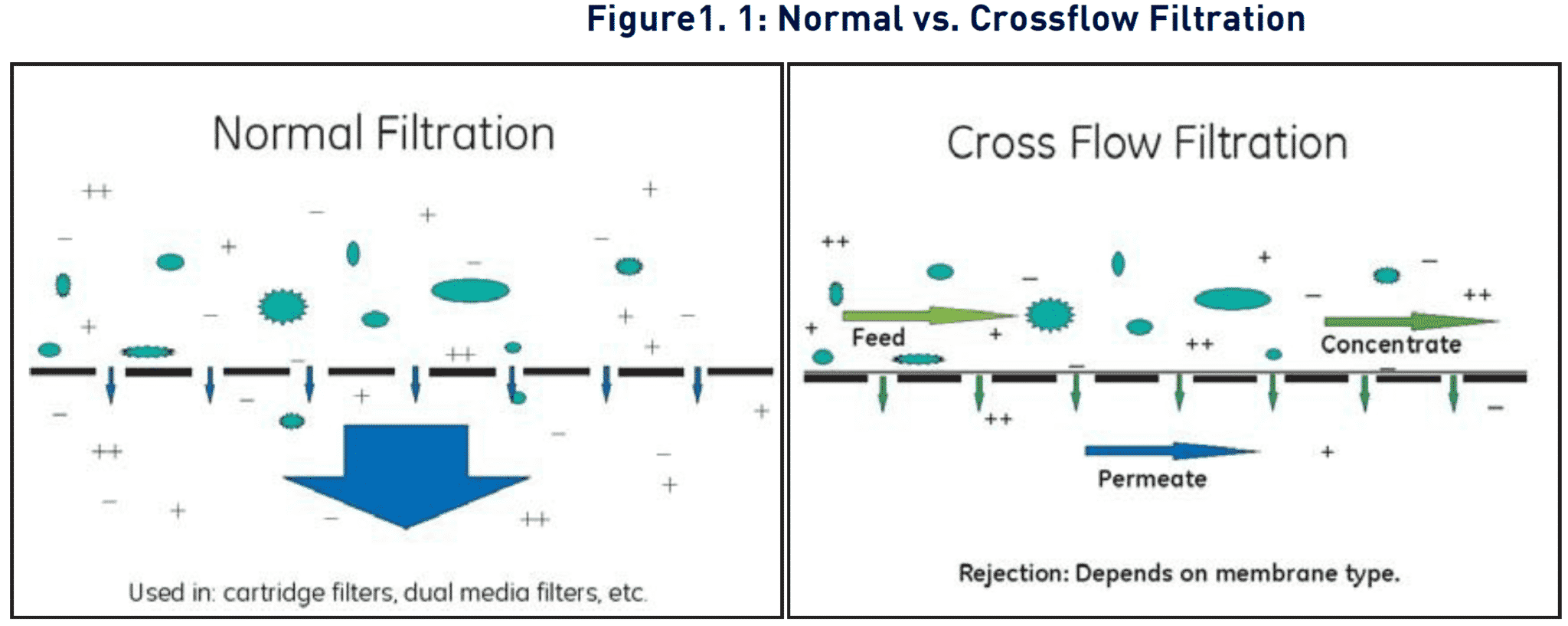
1.1.4 reverse osmosis (RO)
Reverse osmosis is the separation of one component of a solution from another component by means of pressure exerted on a semipermeable membrane. In other words, reversing the natural passage of a liquid from a concentrated solution to a more dilute solution by using external pressure. Removal of ionic, organic, and suspended /dissolved impurities occurs during the RO process. Unlike a filter, which separates by “normal” filtration, the membrane element separates using a process called cross flow filtration. Feed water solution is separated in to two streams, permeate and concentrate, and collected from both sides of the membrane. A semipermeable RO membrane, under sufficient pressure, allows passage of purified water while rejecting and concentrating dissolved and suspended solids.
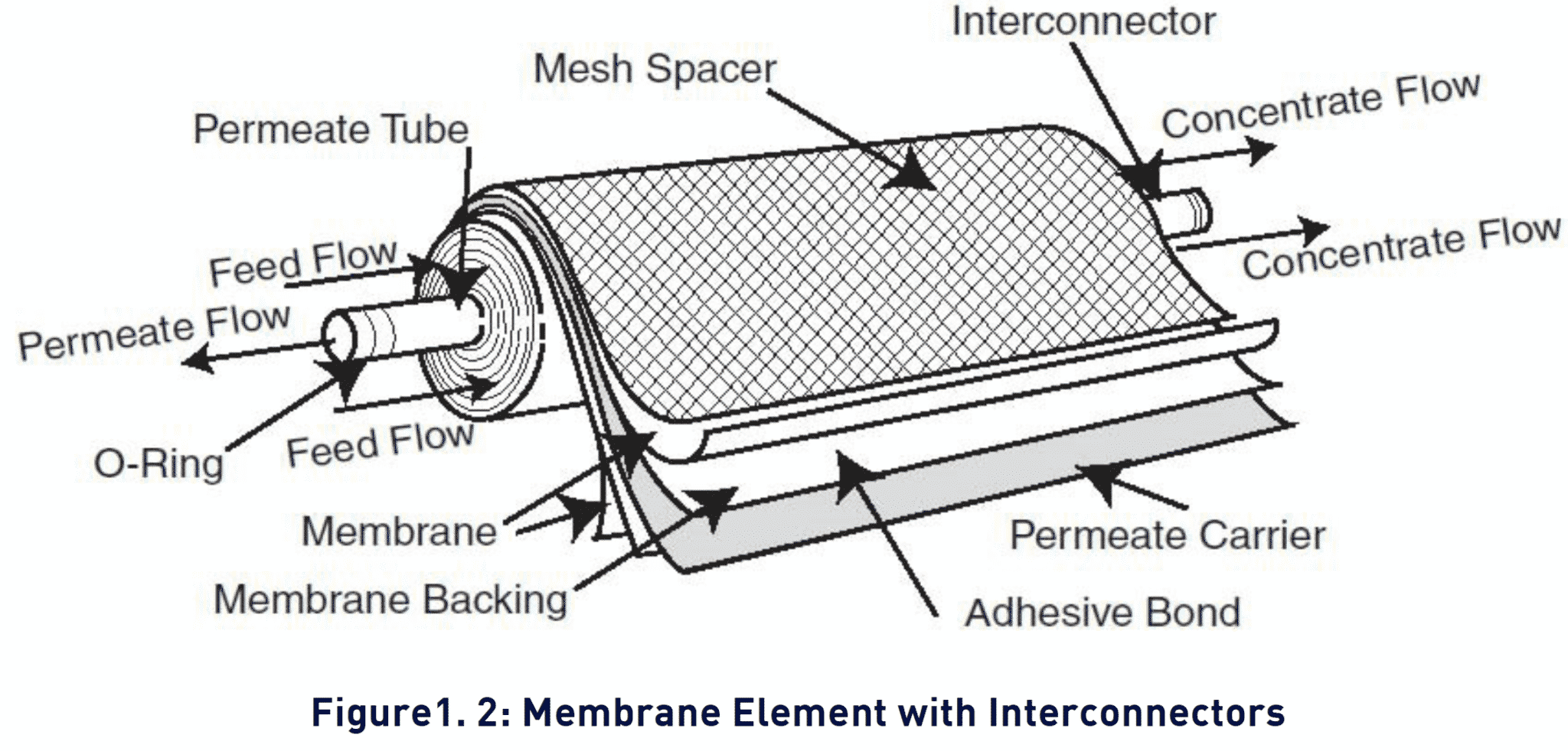
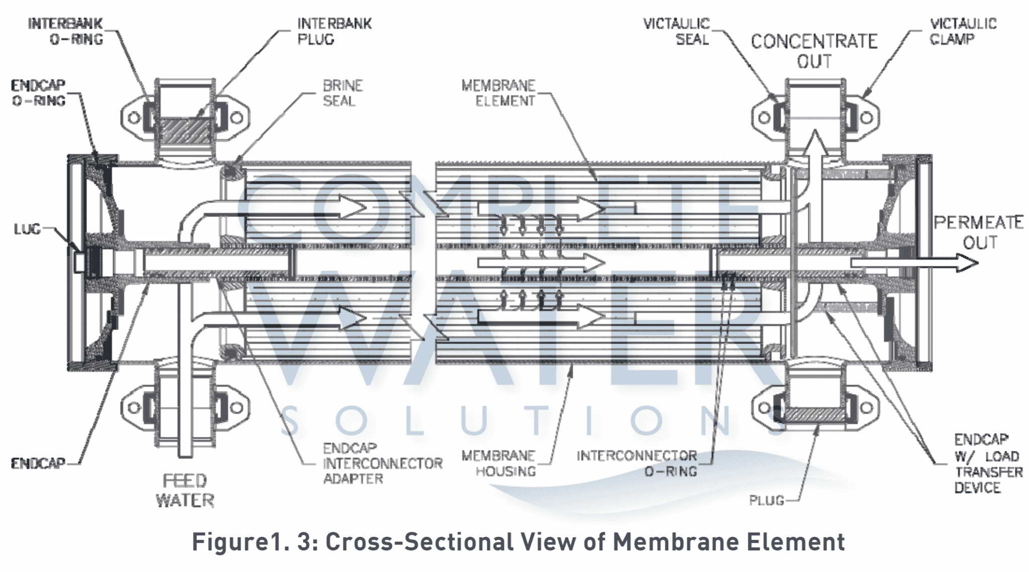
1.1.5 Membrane Elements
Membrane elements are the key to reverse osmosis. Interleaved layers of semipermeable membrane, spacer and permeate carrier spiraled around a central permeate tube make up the element. The spacer allows for movement of the concentrate past the membrane, and the permeate carrier carries the purified water out of the membrane element . Veolia manufactures a patented spiral wound membrane element with a turbulent flow design. This membrane module collects the purified water within the central tube, the permeate tube. The E4H RO machine utilizes between 9 and 24 membrane elements.
1.1.6 CIP
The abbreviation for clean-in-place.
1.1.7 average pressure [PAVG]
1.1.8 Concentration
– Concentration equals the Total Dissolved Solids (TDS) concentration of a solution expressed as parts per million (ppm) or conductivity (microSiemens/cm).
– Cf = Feed Concentration
– Cp = Permeate Concentration Cc = Concentrate Concentration
– Cavg = Average Concentration in Machine
1.1.9 Salt (Ionic) Passage
The percent of dissolved salts passed through the membrane or 100% minus rejection.
1.1.10 Recovery
Permeate rate divided by feed rate, expressed as a percentage. For example, 33% recovery means that for a given feed rate, 33% is produced as purified water (permeate).
1.1.11 Salt (Ionic) Rejection
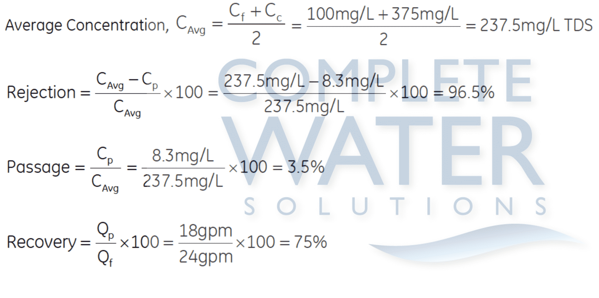
An example of how to calculate salt rejection and recovery is given below.
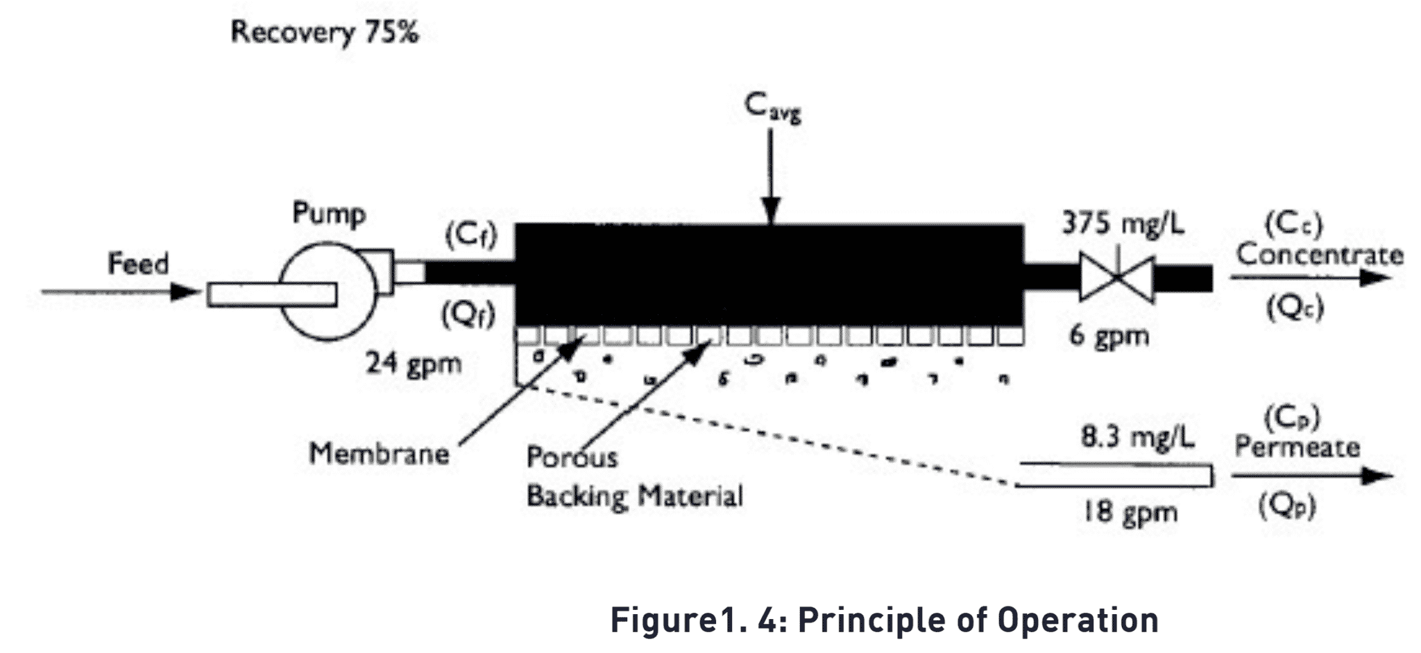
Given the system case in the figure above:
1.2 Flow Description
The feed water passes through a replaceable 5-micron cartridge filter, which removes bulk suspended solids. Filtered water then flows to the inlet control valve.
This solenoid-controlled diaphragm valve is wired to the on/off switch and opens when the machine is turned on, allowing water to flow to the pump inlet. When the machine is turned off, the valve closes, preventing non-turbulent flow through the membrane elements, which would lead to shortened membrane life.
The pump feeds water to the membrane housings arranged in parallel and serial combinations. A throttling valve is included on the pump discharge for manual adjustment of the pump pressure. The direction of water flow is indicated by an arrow on each housing. Water is separated by the membrane within the membranes and leaves the housings in two streams: permeate and concentrate.
Permeate from each membrane housing is collected in a common manifold. The permeate then flows through a flow meter and to the outlet point of the machine.
The concentrate leaves the last membrane housing and flows to the flow control center (recycle/concentrate manifold). At this point, the recycle valve channels a predetermined amount of concentrate into the pump inlet. Recycle increases recovery while maintaining adequate cross-flow through the membranes. The other two ports of the flow control center lead to the concentrate valve and final pressure gauge. The concentrate valve has three functions: It controls the amount of concentrate flowing to the drain; it controls the pressure within the machine; and it helps control the system recovery. A feed flush solenoid is added to the flow control center with an additional tee. The concentrate then flows through a flow meter and to the outlet point of the machine.
1.3 Machine Nomenclature
E-Series water purification machines are numbered in such a way as to indicate the permeate flow you can expect from the machine and other specifications.
Example: RO,E4H-21K-DLX, 460, 6, 50-75
• RO indicates the machine is a reverse osmosis machine.
• E4H indicates the machine series (E) and 4-inch housings/membrane elements
• H indicates horizontal membrane element housing configuration
• 21K indicates the rated permeate flow in thousands of gallons per day at 77°F (25°C),
• i.e. 21K = 21,000 gallons per day
• DLX indicates the deluxe model and ECN indicates the economy model
• 460 indicates 460 VAC, 3-phase voltage to starter. Standard models offer 460 VAC, 60 Hz, 3-phase, 230 VAC, 60
Hz, 3-phase, and 380 VAC, 50 Hz, 3-phase.
• 6 indicates 60 Hz operation, (50 Hz operation is also available and is indicated by a 5 in place of the 6.
• 50-75 indicates a recovery range of 50 to 75%.
1.4 economy (ECN) model and deluxe (DLX) model options
1.4.1 ECN model
E-Series ECN model water purification machines have all the features necessary for safe, continuous production of high purity water. This assumes good quality feed water, adequate pretreatment and regular operator maintenance, each shift or daily, to the operation of the system.
• 50% to 75% recovery
• Multi-stage centrifugal pump, SS construction (stainless steel castings with Noryl* Stages)
• Base model electrical package includes NEMA-1 enclosure with a 110 VAC, 60 Hz or 220 VAC, 50 Hz singlephase
control circuit; applies to all ECN models
• Automatic inlet shutoff valve
• Pre-filter housing and 5-micron cartridge filter
• Pre-filter, post-filter, primary and final pressure gauges
• Concentrate and permeate flow rotameters
• Pump throttling valve
• Digital conductivity monitor, panel-mounted, for permeate quality monitoring
• Feed flush System – programmable, automated high-velocity membrane flushing for the longest membrane
life; set at the factory and adjustable in the field
• Gauges, valves and rigid piping of stainless steel or plastic
• Fiberglass reinforced plastic (FRP) membrane housing, with Noryl end caps
• Stainless steel concentrate and recycle valves
• All components in contact with the purified water (permeate) are either FDA- acceptable plastic (nylon, Noryl,
polypropylene, PVC) or stainless steel materials.
• All high pressure fittings are 304 stainless steel.
• Alarms included: low inlet pressure and motor fault
1.4.2 DLX model
The DLX package contains all of the above ECN standard features along with an AccuTrak* RO solid state controller.
• Electrical package includes AccuTrak* RO controller
• Chemical dosing system for antiscalant or pH adjustment
• Clean-In-Place (CIP) system
• Digital flow meter and conductivity sensor
• Analog pH sensor on inlet
• Alarms included: low inlet pressure, high permeate pressure, high/low inlet pH, high temperature, high
permeate conductivity, fill-time exceeded, and motor faul
1.5 Specifications for E-Series Machines
The machine flow specifications listed in Table 1.1 below are based on 77°F (25°C) and 2,000 ppm NaCl.
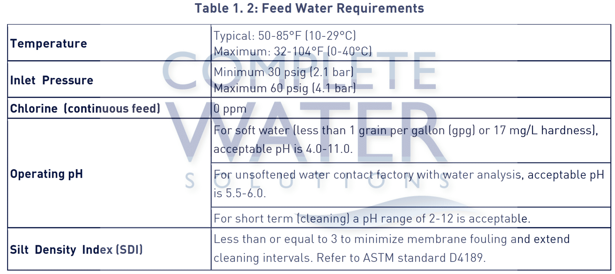
1.5.1 Feed Water Specifications
The feed water requirements stated in the following table must be met to ensure quality permeate and extended membrane element life.
1.5.2 Permeate Flow Rate
Stated in Table 1.1 above and on the machine serial number label (assumes no permeate backpressure, 2000mg/L TDS maximum feed concentration, and rated temperature).
To estimate permeate output with backpressure, use the formula below: Maximum permeate backpressure is 80 psig (5.5 bar).

1.5.3 Concentrate Flow Rate
Stated in Table 1.1 and factory set as stated on serial number label.
1.5.4 Operating Final Pressure
Minimum – 200 psig (13.8 bar)
Maximum – 235 psig (16.2 bar)
1.5.5 Pump
Multi-stage centrifugal; approximate primary operating pressure of 190 psig (13.1 bar) excluding line pressure.
1.5.6 RO Membrane Rejection
E4H reverse osmosis machines use Veolia fiberglass reinforced plastic (FRP) covered AG4040F membrane elements. For ordering information refer to the attached Spare Parts List. See Table 1.3 below for details.
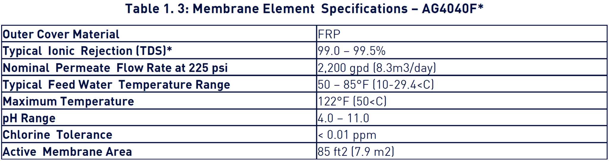
*Specification is based on a 2,000 mg/L NaCl solution at 225 psi (1,551 kPa) operating pressure, 77°F (25°C), pH 7.5 and 15% recovery. Individual flux may vary +25%/-15%. Average salt rejection after a minimum of 24 hours of continuous operation.
2. Installation
2.1 Mounting
E4H Series machines are equipped with a stand-alone frame, which supports the machine. At least 45 inches (114 cm) of space should be allowed on each end of the membrane element housings for removal and loading of membrane elements. If 45 inches (114 cm) are not available, the entire membrane element housing may need to be removed for membrane element replacement.
WARNING!! – A vacuum breaker must be installed at the highest point along the concentrate line. Failure to do so may cause a vacuum to form within this line after shutdown. This may in turn cause numerous problems, including biological fouling, water hammer, leaks from RO housing side- ports, and the siphoning of treatment chemicals.
Connect the concentrate line to the RO machine’s concentrate outlet. A vacuum breaker must be installed at the highest point along the concentrate line. This provides an atmospheric break upstream from where the flow enters the drainage system. For systems which include multiple RO machines, install check valves along each machine’s concentrate line prior to connecting the lines to a common manifold.
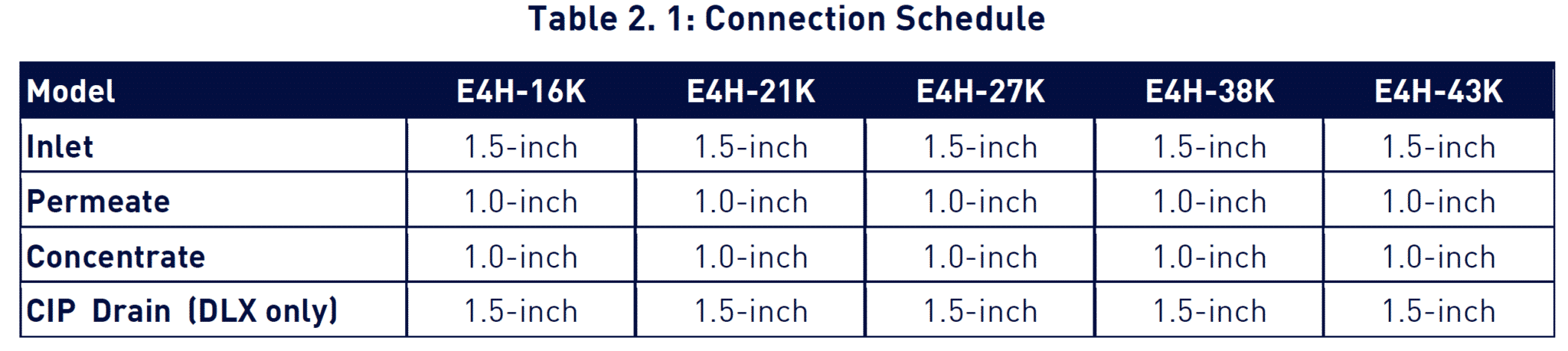
2.2 Piping
The E4H comes with threaded NPT fittings. A CIP system is supplied with the DLX Model E4H.
2.3 Electrical
The DLX and ECN E-Series models are supplied with a single-phase, 110 VAC 60 Hz or 220 VAC 50 Hz control circuit. Refer to your machine electrical single-line drawing for dedicated circuit requirements.
The electrical system control circuit is separate from the motor voltage. Therefore, two supply voltages are required for electrical wiring in the field, the control circuit voltage and a separate three-phase motor voltage. All field wiring must comply with applicable local and national electric codes.
2.3.1 ECN Electrical System
• A panel mounted power on/off switch is provided on the electrical enclosure.
• Connect the control circuit power cord to 110 VAC, 60 Hz, or 220 VAC, 50 Hz, single phase power.
• Connect the three-phase power in to the motor starter 3-pole contacts (230/460 VAC or 380 VAC as appropriate). Ensure that the power supplied matches the motor voltage and phase requirements. Check the tag (located on the motor starter) that indicates the factory wiring. A separate, fused disconnect for the motor wiring is required with proper protection for the HP and amp draw of the RO and CIP motors (provided by others). Please refer to single- line drawing for further detail.
2.3.2 DLX Electrical System
• The DLX series E4H’s include the Burkert. The Burkert includes a menu screen for selecting the operation mode of the RO. The RO must be in either “Auto” or “Hand” position for the high pressure pump to start.
• Connect the control circuit power to 110 VAC, 60 Hz, or 220 VAC, 50 Hz, single phase power.
• Connect the three-phase power in to the motor starter 3-pole contacts (230/460 VAC or 380 VAC as appropriate). Ensure that the power supplied matches the motor voltage and phase requirements. Check the tag (located on the motor starter) that indicates the factory wiring. A separate, fused disconnect for the motor wiring is required with proper protection for the HP and amp draw of the RO and CIP motors (provided by others). Please refer to single- line drawing for further detail.
3. Preparation
3.1 pretreatment for water purification
All systems will operate most efficiently on filtered water with a pH of less than 6.5 and a Silt Density Index (SDI) of 3 or below. If the machine is operated on higher pH water, other forms of pretreatment may be necessary. A water analysis prior to start-up of the machine is required. To minimize the chances of calcium carbonate, calcium sulfate, or other salt precipitation on the membrane, Veolia strongly suggests that each application and water condition be evaluated so that specific recommendations can be made to ensure continuity of the membrane warranty. Data from the water analysis is processed with a computer program analysis to determine if potential problems exist. I the machine is to be run at a different location than was originally intended, a new water analysis is required for warranty consideration and should be sent to Veolia for review and recommendations for operation of the machine.
Before entering the machine, the feed water must be filtered to 5-microns.
TFC membrane feed water must not contain the following chemicals or permanent loss of rejection and/or permeate flow may result:
• Free chlorine
• Formalin (until after a membrane has been run for 24 hours; thereafter, 0.5%- formaldehyde may be used as a biocide)
• Iodine compounds
• Quaternary germicides
• Cationic surfactants
• Detergents containing non-ionic surfactants
• Cleaners not approved by Veolia
CAUTION! – A water softener should not regenerate while the machine is running unless safeguards are used to be sure the machine is operated on softened water during regeneration.
3.2 Start-Up
NOTE – If your machine is provided with the membranes installed in the housings, proceed to step 1. If your machine is provided with the membranes in shipping boxes, you must load the membranes in the housings prior to starting the machine. For membrane loading instructions, skip to Section 4.6. Upon completion of membrane installation, return to section 3.2 to continue your start-up procedure.
1. Re-check the function and integrity of your pretreatment equipment. Ensure that your water softener, activated carbon filters and iron filters (where applicable) have been leak-checked, backwashed, and thoroughly rinsed for service before starting up your RO unit.
2. Attach the feed water pipe to the inlet of the machine.
3. Check for leaks at all connection points.
4. Turn on the feed water gradually and check for leaks in the inlet piping. No flow should go through the machine while the power is off and the inlet solenoid is in the closed position.
NOTE – When the machine is off, there should never be flow through the machine. Flow through the machine when it is off can damage the membranes, and the inlet solenoid must be repaired
5. Attach tubing from permeate and concentrate outlet points, and run the tubing to drain.
6. Ensure that you have made provisions for both voltages required to operate your machine. The machine requires two power sources: (1) the high voltage for the motor operation, and (2) the control circuit power supply. The motor electrical service must be field-wired directly into the motor starter on the machine. Bring your motor service wiring to the 3-pole contacts on the motor starter. Check the voltage label to ensure that you have brought the correct voltage to the starter.
7. Be sure the power to the motor starter is de-energized.
8. With the machine in the OFF position, connect the 110 VAC (or 220 VAC 50 Hz) wiring.
9. Open your concentrate and recycle flow control valves two complete turns. These valves are positioned on the flow control center of the machine. This piping is located on the left section of the machine, near the membrane housings. The flow control center features a concentrate flow control valve, a recycle flow control valve, and a pressure gauge sensor tubed into the panel-mounted pressure gauge.
NOTE – The feed flush valve is positioned in this flow control center.
The proper adjustment of these valves is critical to the operation of the RO machine. The concentrate valve determines the amount of rejected water leaving the machine, and creates the operating pressure shown on the pressure gauge. The recycle valve returns reject flow back into the inlet stream to the RO pump. It is important to balance the operating pressure and the respective flows of these valves to ensure that your machine is operating correctly. It is also important to understand the relationship of these two valves, the pressure gauge, and your RO pump. The pump has a fixed amount of flow produced, and the valves are the control devices to distribute this fixed flow amount. The pressure gauge is an indicator of applied membrane pressure, at the flows set by the valves.
10. For ECN machines (skip to step 14 for DLX) – Turn the panel switch to the ON position. Water will begin to flow
through the machine at this point, but the pump will not start. Allow the machine to operate in this manner for
10 minutes, to purge the air out of the machine.
NOTE – The high-pressure pump should not be operating at this time.
11. As your machine is filling check for leaks and repair as needed.
12. Turn the panel switch to the OFF position.
13. Energize the power source to the motor starter. The pump should not operate at this point. Skip to step 18 to continue with startup procedures.
14. For DLX machines – Energize the power source to the motor starter. The pump should not operate at this point.
15. Select Fill mode on the AccuTrak RO controller. Water will begin to flow through the machine at this point but the pump will not start. Allow the machine to operate in this manner for 10 minutes, to purge the air out of the machine. Verify alarm set points in the AccuTrak RO controller.
The factory alarm set points are as follows: (consult the AccuTrak RO Multifunction Water Treatment Controller Manual for operating instructions and additional information).
– Low Inlet Pressure 12 psig High Permeate Pressure 80 psig
– Permeate Conductivity 200 μS (microSiemen) Low pH 4.0
– High pH 8.0
– pH Control 5.6-6.2
– High Temperature 104°F (40°C)
16. As your machine is filling check for leaks and repair as needed.
17. Turn the AccuTrak RO controller to the OFF position.
18. Check the rotation of the high pressure pump by briefly turning the RO System Selector switch to the MANUAL position. Watch the motor, or coupling shaft, for direction of rotation. The motor should rotate clockwise as one looks at the motor end of the high pressure pump. If the motor is not rotating clockwise, change any two of the three leads (for three-phase) in the motor starter and recheck rotation. Always turn the power off to change any wiring.
CAUTION! – Operation of the pump backwards for even a short time can cause damage to the pump.
Turn the RO System Selector to the MANUAL position. The high-pressure pump will operate and the machine will begin to build pressure. As you are operating, be sure to watch the pressure gauge on the instrument panel. The machine is designed to operate at 220 psi (15.2 bar).
NOTE – Do not allow the pressure to exceed 250 psi (17.3 bar). If the pressure exceeds 250 psi (17.3 bar), open the concentrate flow control valve until the pressure gauge shows 250 psi (17.3 bar) or less.
As the machine purges the air and fills with water, the pressure will gradually increase. You should see water flowing through the permeate and concentrate flow meters. If you do not see flow, turn the machine off and return to step 1.
NEVER ALLOW THE MACHINE TO OPERATE WITHOUT ADEQUATE WATER PRESSURE. THIS CAN CAUSE SEVERE DAMAGE TO THE HIGH-PRESSURE PUMP.
19. Gradually close the concentrate flow control valve. As you close the valve, watch the pressure gauge and your concentrate flow meter. Close the valve until your concentrate flow meter displays your design flow, and you do not exceed 250 psi (17.3 bar). If you reach 250 psi (17.3 bar) before the valve is completely closed, open the recycle flow control valve one full turn, then continue to close the concentrate flow control valve. Continue to close the concentrate flow control valve until it is completely closed and your pressure is below 250 psi (17.3 bar).
The concentrate flow control valve has a drilled orifice to ensure a predetermined amount of flow and pressure in the closed position. This orifice is sized to operate the machine at 75% recovery.
20. With the concentrate flow control valve fully closed and the pressure below 250 psi (17.3 bar), gradually close the recycle flow control valve until the pressure reaches 250 psi (17.3 bar).
Your machine is now operating at the design pressure and flow rates in a 75% recovery configuration. Your specific needs or conditions may dictate the need to operate the machine at a lower recovery. If you wish to operate in a recovery configuration lower than 75%, step 19 will explain the necessary steps.
21. Your machine is equipped with flow meters and a pressure gauge that will assist you in setting alternate flow rates for variable recoveries. If you wish to operate at a recovery lower than 75% you must ensure that the flow rates for the permeate and concentrate are at desired levels. Some minor adjustments in the concentrate and recycle flow control valves may be necessary.
See Table 1 for specified flow rates for various machine recoveries. When you have selected your desired flow rate, gradually adjust the concentrate flow control valve to achieve desired flow and use the recycle valve to bring the operating pressure up to 250 psi (17.3 bar).
Once the desired flow rate is achieved [250 psi (17.3 bar) operating pressure] no further valve adjustment is needed.
NOTE – Permeate flow rates are dependent upon temperature and conditions at your site. Contact your dealer if you have any question
22. The system is now operational.
23. Before putting the machine into final operation, continue to run the permeate and concentrate streams to drain for at least 30 minutes. This is done to ensure that all of the bactericide has been removed from the embranes.
24. Connect the permeate line to the point of use of the permeate. Check for leaks and ensure that you have no kinks in hoses, or blockage of any piping on the permeate and concentrate outlet lines.
25. Make any necessary final adjustments to flows and pressure according to step 17.
26. NOTE: The membrane(s) in your machine are rated for certain flow rates at 77ºF (25ºC). Maximum flow rates are achieved when the membranes have been completely rinsed and on-line for at least 24 hours. 27. Record all operating parameters at initial startup on a log sheet. A start up data log sheet is included in section 9.3 of this manual.
28. A daily log sheet, which includes general operating conditions (pressures, flows, concentrations, pH, and pretreatment conditions), and routine or special maintenance (flushing or cleaning as needed) must be kept . This log sheet will be required by Veolia if a warranty question arises.
4. Operation and Maintenance
The operation and maintenance of your Veolia E4H Machine is relatively simple but requires regular data recording and routine preventative maintenance. We cannot emphasize too strongly the importance of filling out the daily log sheet during each operating shift. A data sheet should have been filled out upon start-up containing pertinent facts on the operation of your machine. These two records are invaluable in diagnosing the performance of the equipment and must be kept for reference.
If you have questions concerning the operation of your machine or the method of data recording, contact the Veolia Technical Support Team. The three preventative maintenance procedures, which must be done on a regular basis are as follows:
1. Change the pre-filter cartridge.
2. Flush the machine daily.
3. Clean the machine with approved Veolia cleaners.
See the following sections for specific maintenance procedures.
4.1 Daily Log Sheets
A daily log sheet, which includes general operating conditions (pressures, flows and concentrations) and routine or special maintenance (pre-filter changes, flushing, cleaning, etc.) must be kept. Copies of the log can be made from the template. A copy of this log sheet will be required by Veolia if a warranty question arises.
4.2 Pre-Filter
A 5-micron pre-filter is factory-installed to protect the membranes and valves from particles, which may be in the feed water. The pre-filter uses two 20-inch (50.8-cm) diameters, 2- micron nominal rated cartridges. To order replacements, see the standard parts list.
The filter cartridges must be replaced, at a minimum, once per week or after every 100 hours of operation, whichever comes first. A pressure drop of 8 psig (0.6 bar) across the filter or more during operation indicates one or more cartridges need changing. Use only Veolia approved filters rated for 5 microns or less. Do not attempt to clean used filters – install new replacements.
!IMPORTANT! – Failure to change the filter according to these requirements will void the warranty.
4.3 Flushing
The machine should be flushed periodically to remove sediment from membrane surfaces.
NOTE – The feed flush system automatically flushes the machine at shutdown when the RO System Selector is set to AUTO mode in the deluxe version and when the ON/OFF switch is set to ON in the economy version. This eliminates the need for frequent manual flushing.
To flush the unit:
1. Open the concentrate valve until the pressure gauge indicates the minimum pressure designated on the
nameplate. This increases the flushing action on the membrane.
NOTE – If pressure will not decrease to designated pressure, or if the concentrate rate does not increase when the valve is opened, the valve may be plugged.
Operate the machine at the designated minimum pressure for 10 to 20 minutes.
CAUTION – Do not operate the machine below the designated pressure without approval from Veolia. Operation below the stated pressure may be detrimental to the pump.
1. Return the concentrate valve to its previous position
4.4 Cleaning
Cleaning the E-Series machine on a regular basis is vital. Over time, contaminants build up to form a layer on membrane surfaces, reducing the permeate flow and quality. If this buildup is not removed from the membrane, it may cause permanent chemical damage and reduce membrane life. A decrease in permeate flow and/or rejection of salts, or an increased pressure drop across the machine will indicate when cleaning is required. Cleaning may be required as often as once every week or as infrequently as every three months, depending upon the local water supply conditions. Veolia recommends cleaning at least once a quarter to assure good membrane element performance and long membrane element life.
4.4.1 Cleaning Procedure For DLX and ECN Models:
1. With the RO machine running, open the CIP permeate valve. After this valve has been opened, close the permeate service valve. Permeate water will flow into the CIP tank. Allow the water to run through the CIP tank and the CIP tank drain valve for a few minutes to ensure the tank is rinsed thoroughly.
After a minute or so, close the CIP tank drain valve. The CIP tank should begin to fill with RO permeate. When the CIP tank has filled to the indicated full line, turn the RO System Selector on the AccuTrak RO controller (DLX model) or the ON/OFF two position power switch (ECN model) to the OFF position.
2. While the machine is OFF, open the CIP inlet valve. Divert the permeate and concentrate streams to the CIP tank for recirculation. Ensure that the pre-filter is clean. A CIP pump (supplied with DLX models only) is recommended to supply feed pressure into the machine
3. For DLX models only – ECN models go to step 4: Highlight CIP Pump on the AccuTrak RO controller and select AUTO mode. Next, highlight RO system and select CIP mode and recirculate the cleaning solution through the machine. It is best to clean at temperatures of 100°F to 110°F (38°C to 43°C), but lower temperatures will suffice. The cleaning solution should be recirculated for approximately 15 minutes or until the solution temperature reaches a minimum of 85°F (29°C). Do not allow the cleaning temperature to exceed 110°F (43°C).
Highlight the CIP and RO System Selectors and select the OFF mode and allow the membranes to soak in the solution for approximately 10 minutes. If heat rise occurs too quickly, larger volumes of cleaning solution or the use of a heat exchanger will slow the temperature rise. Turn the CIP off and allow it to soak for 10 minutes.
CAUTION – Do not operate the machine below the designated pressure without approval from Veolia. Operation below the stated pressure may be detrimental to the pump.
For ECN model only:
4. The ECN model does not include a CIP pump. You will need to install a CIP pump, a CIP pump motor starter with a manual start/stop switch, plumb a CIP recirculation line back to the CIP tank, a CIP recirculation hand valve, and a CIP recirculation pressure gage located after the CIP pump but before the CIP recirculation hand valve in order to have the necessary equipment to perform the cleaning process.
Connect the CIP pump discharge plumbing to the Victaulic fitting on the CIP inlet just upstream of the RO pre filter. Connect CIP concentrate and permeate hoses from the RO to the CIP tank (supplied by others). Open the CIP recirculation valve so as to create 15 psig back pressure to the CIP pump. Turn on the CIP pump and recirculate the cleaning solution in the CIP tank for 5 minutes.
Open the CIP hand valve to the RO inlet line. Turn the panel two-position power switch to on and recirculate the cleaning solution for 15 minutes or until the solution temperature reaches 100°F (38°C). Do not exceed 110°F (43°C). The membrane elements can only handle temperatures in excess of 85°F (29°C) for short periods of time. If the cleaning solution temperature rises too quickly then use a heat exchanger to control high temperature swings.
Turn off the RO high pressure pump by turning the panel two-position power switch to OFF and turn off the CIP pump. Allow the RO to soak for 10 minutes.
5. To flush the detergent from the machine, close the CIP inlet valve and divert the permeate and concentrate to drain by opening the CIP drain valve. Highlight to RO system and select MANUAL mode on the AccuTrak (DLX model) or turn the panel two-position power switch to ON and flush the RO machine for one hour. The detergent is sufficiently flushed when the permeate conductivity is restored to nearly its previous level.
6. To return the RO to service, open the permeate, concentrate valves so that flow is routed as intended in the service mode. Close the CIP permeate, CIP concentrate valves. The RO is now ready for operation.
4.5 Draining Machine for Storage/Shipment
Prior to shipping or outside storage of a Veolia E4H Machine, the system should be cleaned with the appropriate cleaner, flushed with water, and protected from biological attack with the appropriate solution for TFC membrane. The membrane housings and piping lines of the machine must be completely drained. Any water remaining in the piping of a machine may freeze, causing damage to the piping, pump, membranes, etc. The party shipping or storing the machine is responsible for any damage resulting from freezing.
1. Disconnect the inlet,concentrate and permeate outlets.
2. Drain all water from the cartridge filter housing.
3. Remove the tubing connections on the inlets and outlets of the membrane housings.
4. Open the concentrate valve.
5. Remove the drain plugs from all PVC manifolds.
6. Be sure the flow meters are drained by disconnecting the bottom fitting of each meter.
7. Allow the machine to drain for a minimum of eight hours or until the opened ports quit dripping.
8. After draining is complete, reconnect all of the piping.
4.6 Membrane Installation
For machines with membranes not loaded at the factory, the following steps are to be used for installation.
CAUTION – The membrane is packaged in a small amount of bactericide solution to prevent biological growth; provide adequate ventilation when handling. The membrane must be kept moist at all times in order to prevent possible damage to the membrane material.
1. Remove the membrane bag containing the membrane from the shipping tube.
2. Cut the bag open as close as possible to the seal at the end of the bag, so that the bag may be re-used if necessary.
3. Remove the membrane from the bag and remove the foam protectors from each end of the membrane.
4. Remove the parts from the parts container (if included) and inspect.Make sure that all parts are clean and free from dirt. Examine the O-rings, brine seal, and permeate tube for nicks or cuts. Replace the O-rings or brine seal if damaged. Set the membrane aside in a clean space and continue on to step 5.
5. Remove the end caps from both ends of all membrane housings on your machine. This is done by loosening the clamp bolts at each end cap closure assembly.
6. Determine the direction of fluid flow in the membrane housing. (Be certain to look at the “Direction of Flow” arrow for each membrane housing. Direction of flow may vary within a given machine.)
7. Inspect the membrane housing and clean as necessary to remove any contaminants, obstructions, etc.
8. Apply a small amount of O-ring lubricant to all O-rings on the end caps, and the brine seal on the membrane.
9. Insert the downstream end of the membrane in the upstream end of the membrane housing (i.e., load in the direction of flow; the brine seal is on the end of the membrane that goes in last.For membrane housings with the flow arrow pointing up refer to step 11).
10. Insert the membrane in the membrane housing with a smooth and constant motion. When you reach the point where the brine seal is about to enter the housing, gently turn the membrane to ensure the brine seal enters the housing without coming out of the brine seal groove.
11. When all of your membranes are installed, you must close the membrane housing package by re-installing the end caps and clamps. It is preferred to install the bottom end cap first, and tighten the clamp completely, before installing the top end cap.
12. Re-install the end caps by gently twisting the end cap while pushing it on to the permeate tube. Ensure that you do not pinch or fatigue any O-rings while pushing the end cap on. Push the end cap on until the outer diameter of the cap is flush with the outer diameter of the membrane housing. Install the clamp halves, and tighten the bolts until the clamp halves meet.
13. Re-connect any fittings that were removed when disassembling the membrane housings.
14. Return to step 1 in Section 3.2 in the Start-Up Procedure.
4.7 Membrane Replacement
As time progresses, the efficiency of the membrane will be reduced. In general, the salt rejection does not change much until two-three years after installation, when operated on properly pretreated feed water and when routine maintenance is performed. The permeate flow rate will begin to decline slightly after one year of operation but can be extended with diligent flushing and cleaning of the machine. High pH feed water and/or precipitation of hardness can cause premature loss in rejection and even flow rate. The following procedure is to be followed to replace existing membranes in the machine.
1. Remove the end caps from all of the membrane housings.
2. Remove all of the membranes from the membrane housings in the direction of flow where possible. If necessary, a membrane can be removed against the direction of flow. A heavy duty pliers or channel lock pliers may be necessary to pull the old membrane out of the membrane housing.
3. To re-install replacement membranes, follow Sections 4.6.
NOTE – Do not operate the machine on water over 85°F (29°C).
NOTE – Do not allow the machine to freeze unless it is totally drained. It must thaw a minimum of 24 hours before starting.
5. Optional Accessories
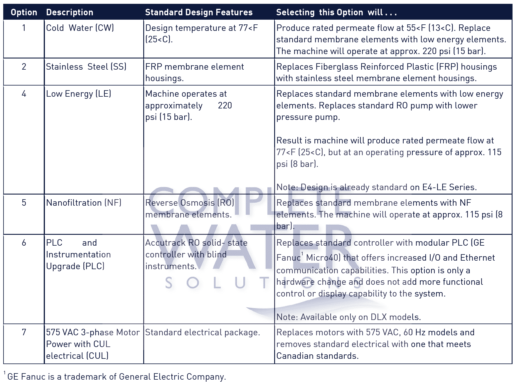
5.1 Standard Options
The following optional features are available upon request. Selection of these options will not affect the start up or operating procedures described above.
5.2 External Controls
Your E4H RO machine is equipped with External Control capability. External Control is the on/off control of the RO via a signal from a remote device. The External Control could be remote on/off, level control, pre-treatment lockout, and/or post-treatment lockout, etc. Utilization of this feature requires a customer-wired control loop, wired to factory-supplied terminals. Refer to either the DLX or ECN electrical drawings for proper wiring and/or electrical connections.
5.3 Filters and Water Softeners
Back-washable filters and softeners should be installed such that unfiltered or un-softened water will not be fed to the machine while the RO unit is operating. Failure to do this may cause fouling or precipitation of calcium carbonate or other materials onto the membranes.
5.4 Storage Tanks
Fiberglass, polyethylene and stainless steel storage tanks are available. All tanks are available with fittings installed at the factory. These tanks must be installed with even support along the bottom.
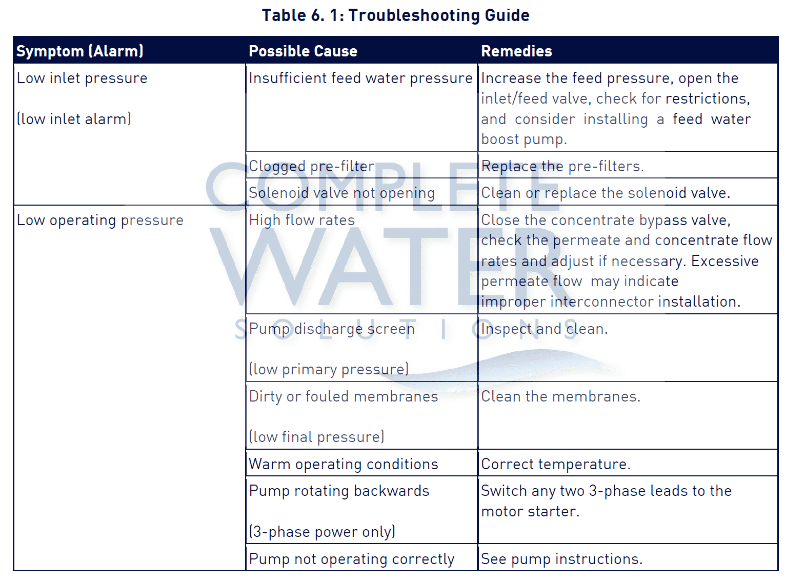
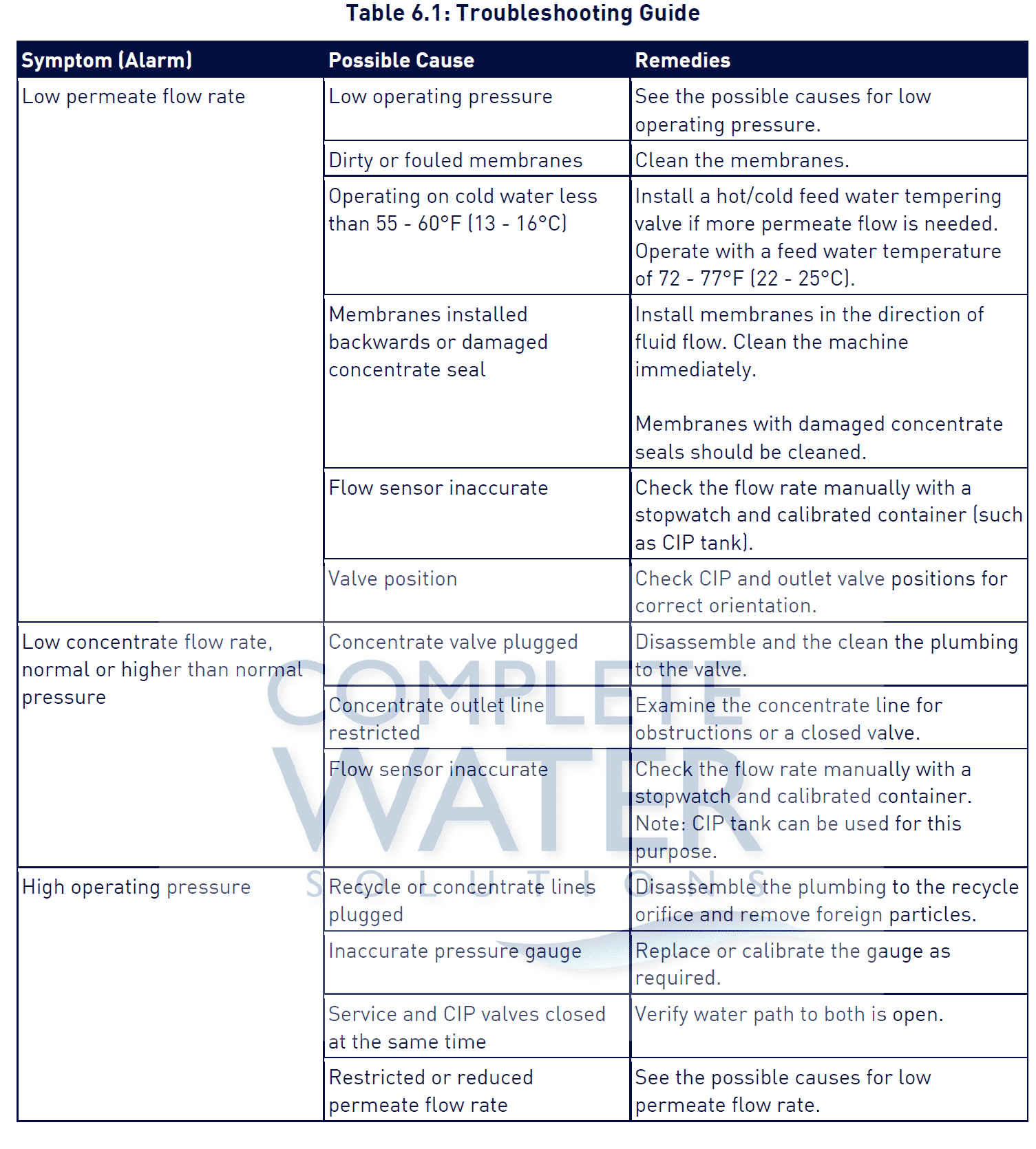
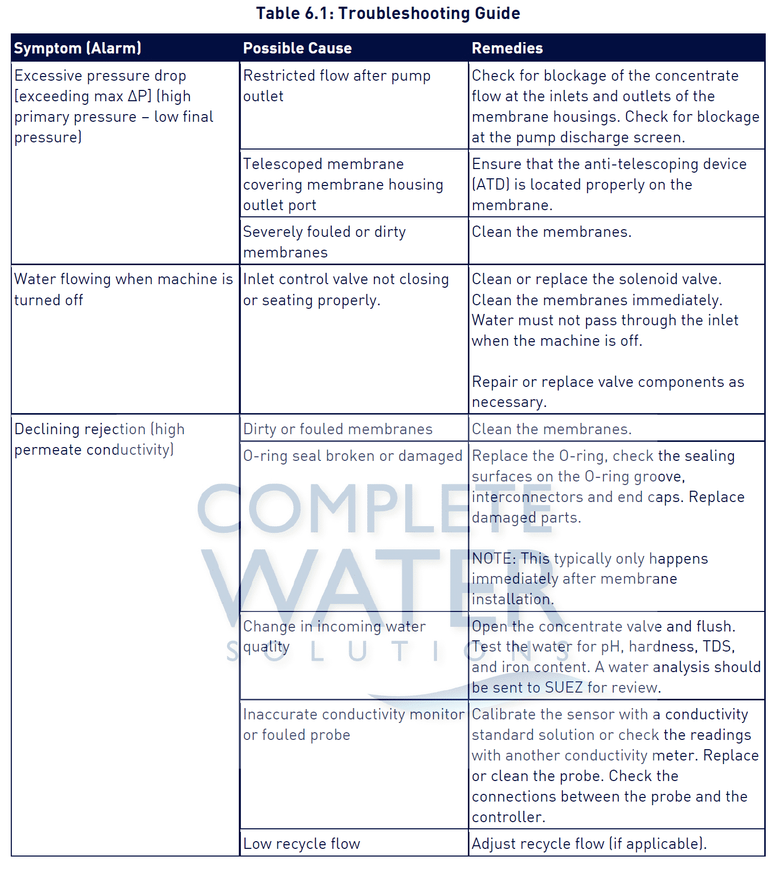
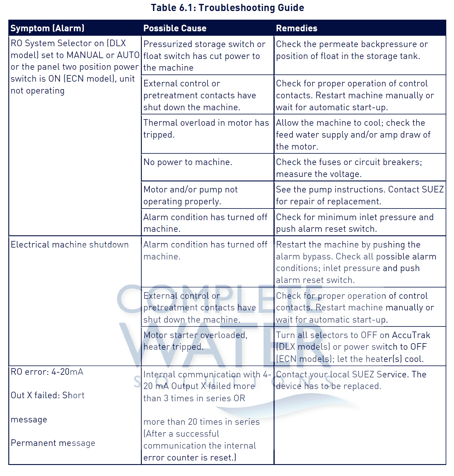
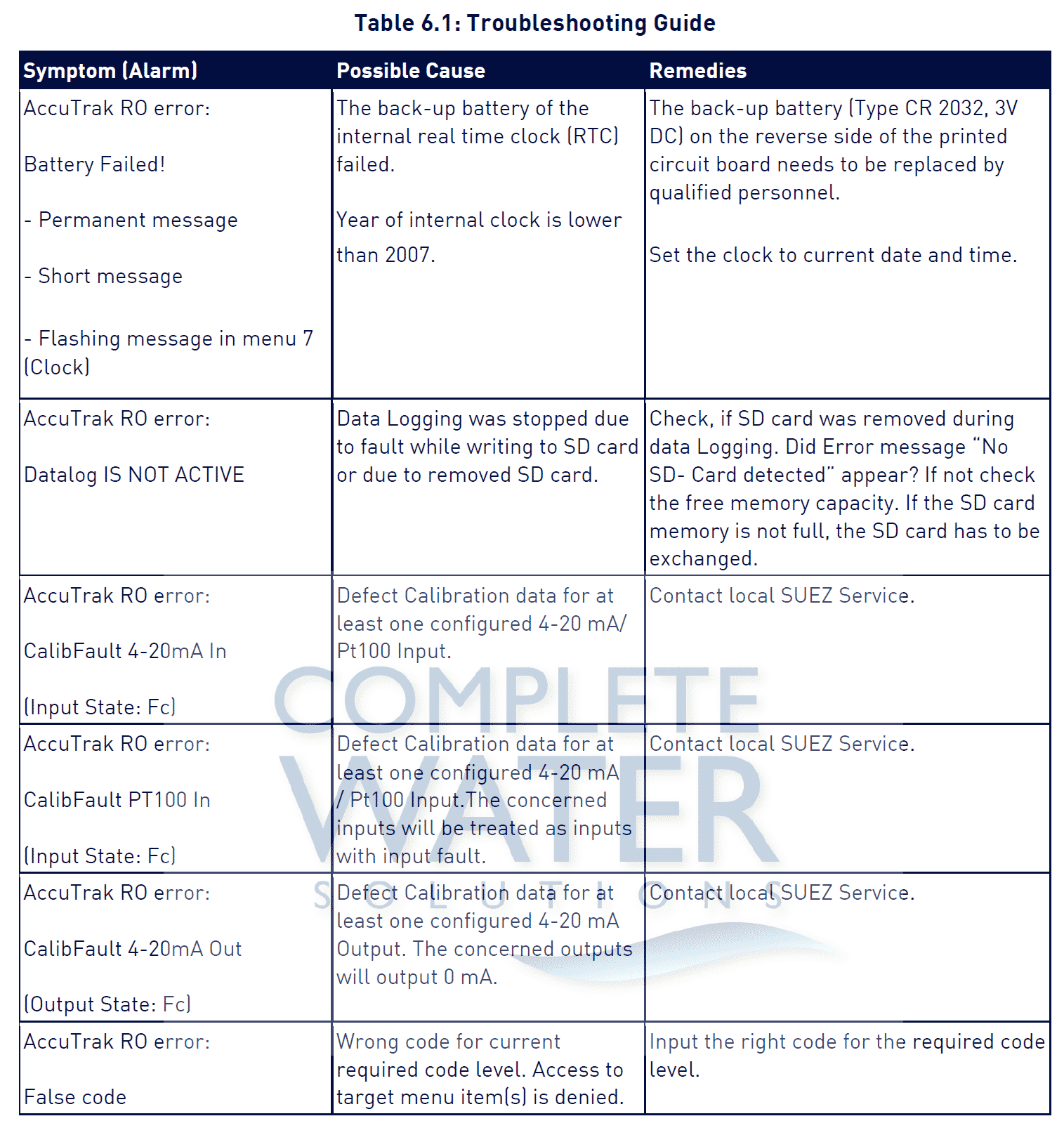
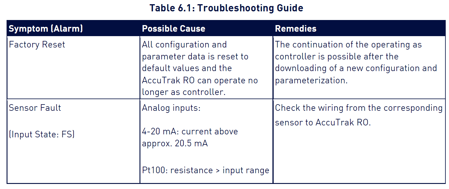
6. Troubleshooting
This troubleshooting guide can assist you in identifying common operating problems you may experience with your machine. The operator can easily correct many of these problems; however, for those that persist or are not understood, you should contact the Complete Water Solutions technical support team (855) 787-4200. Have the following information available when calling the CWS technical support team:
• Machine installation date.
• Model number (found on right-hand side of front panel).
• Serial number (found on right-hand side of front panel).
• Daily Log Sheets.
• Detailed description of problem.
7. Spare Parts List
For detailed spare part lists, please refer to the manual addendum. Contact the CWS Customer Support Center to order parts. (855) 787-4200 info@complete-water.com
8. Return Goods Authorization (RGA) Procedure
If you wish to return goods for repair, warranty evaluation and/or credit, please have your original sales order or invoice available when you call CWS. Call the CWS technical support team at 1-855-787-4200. A CWS technical support representative will provide instructions and a return authorization number, which needs to be clearly written on the outside of the box used to ship your materials. All equipment must be shipped to CWS with the freight prepaid by the customer. Call our Customer Support Center with any questions or issues concerning freight claims and a representative will discuss your situation.
!IMPORTANT! – Machines must never be shipped with water in them; this will void the warranty. Drain the machine completely before shipping a n d avoid freezing before draining. The machine should be sanitized prior to draining. Refer to the draining and cleaning instructions in this manual for details.
9. Warranty/Guarantee
9.1 Machine Warranty/Guarantee
Seller warrants its products to be free from defects in material or workmanship for a period of 15 months from receipt or 12 months from start-up/first use of the product , whichever occurs first , but only when said products are operated at all times in accordance with Seller ’s written instructions. This warranty does not apply to replaceable parts or components normally subject to wear and replacement.
Unless stated specifically on a form, official “Performance Warranty Document” signed by an officer or director level employee of the Seller and an employee of the Buyer who is authorized to make such representations, there is no performance warranty on products or warranty on process results.
Seller expressly disclaims liability for incidental and/or consequential damages including, without limitation, lost profits. This warranty is made expressly in lieu of all other warranties, express or implied, including all implied warranties of merchantability or fitness for any particular purpose. Buyer assumes all liabilities for use and misuse by buyer, its agents or assignees.
Buyer shall give immediate notice in writing to Seller if products or components thereof or performance (where applicable) appear defective, and shall provide Seller with reasonable opportunity to make inspections, tests, and repairs using the most efficient and cost effective methods available for such products or components. If Seller is not responsible under the terms of this document and/or any formal performance warranty, Buyer shall pay Seller the costs and expenses of such inspections, tests, and repairs.
Seller’s obligation under this warranty is limited to repair or replacement at its factory, for the original user, of any product or component part thereof, which shall prove to have been defective. No allowance will be made for repairs or alterations made by the Buyer without the Seller’s written consent or approval.
In no event shall Seller be liable to Buyer for any amount, including costs incurred or expended by Seller in attempting to correct any product deficiency, relating to any claim by Buyer against Seller in excess of the aggregate total purchase price under this contract. No charges or expenses incident to any claim will be allowed. The remedies provided herein are exclusive, and Seller shall incur no liability other than that stated herein.
Goods may not be returned to Seller without Seller’s written permission. Seller will provide Buyer with a RGA number to use for returned goods. All returns shall have freight and related costs prepaid by Buyer from point of origin. Seller is not responsible for meeting state and local codes or ordinances, or other special codes not specifically stated in writing on the purchase document or contract.
TECHNICAL ADVICE – Seller may, at Buyer’s request, furnish technical assistance, advice and information with respect to the products supplied under this contract, if and to the extent that such advice, assistance, and information are conveniently available. Seller has no obligation to provide such information, which is provided without charge at the Buyer’s risk, and which is provided subject to the limited warranty above.
9.2 Desal membrane element workmanship warranty
Veolia Osmonics, Inc. guarantees the proposed product to be free from defects in material or workmanship when operated in accordance with written instructions for a period of one year from start-up or fifteen months from receipt,whichever is shorter. Parts not manufactured by Veolia Osmonics are covered by their manufacturers’ warranties that are normally for one year.
Veolia Osmonics spiral-wound membrane elements are guaranteed to operate within specifications when used for general water treatment for a period of 12 months from receipt providing the membrane elements have not been abused by operating at high temperatures, high or low pHs, on disinfected water, or on solutions which tend to precipitate. For applications or water conditions other than those specified in the original purchase order for the reverse osmosis or ultrafiltration machine, the User should consult Veolia Osmonics’ Engineering Department as to the suitability of the solution to be run in the membrane elements.
Limitations on pH and temperature can vary with membrane type and the application of the equipment . For general water treatment , pH should be kept between 3.0 and 7.0 with a temperature below 85ºF (29ºC) unless specifically designed for higher temperatures. For special applications or for pH or temperature ranges outside the stated limits, Veolia Osmonics may reduce the warranty period.
A membrane element which fails to perform satisfactorily within the first 90 days after receipt , has not been mishandled, and is returned to the factory, will be replaced free of charge except for freight and local labor. If a membrane element fails to perform satisfactorily during the balance of the warranty period and with the return of the membrane element to the factory, Veolia Osmonics will replace the membrane element with a new membrane element and will charge the User for the portion of the 12 months that the membrane element was used plus incoming freight and local labor. Such prorated charges will be based on the list price prevailing at the time of warranty consideration. A new membrane element supplied under warranty terms will carry the standard 12- month new membrane element warranty. If membrane elements have not been placed in use at the end of the permissible storage period, the date of first use shall be considered to start the end of the permissible storage period.
The customer shall be responsible for acceptance testing for the membrane elements received to ensure that they meet the published performance specifications. Veolia Osmonics shall be notified within thirty (30) days for first use of any membrane element not meeting specifications. Should Veolia Osmonics not receive notification of noncompliance with performance specifications within said thirty (30) day period, Veolia Osmonics will consider that all membrane elements are accepted.
All membrane elements being returned for non-warranty issues or credit for unused membrane elements must be returned unused in their original packing. Membrane elements returned not conforming to said criteria will be subject to rejection or added fees to restore membrane elements to sellable condition.
Veolia Osmonics warrants storage of membrane elements as follows:
1. All dry membrane elements (excluding cellulosic elements) for six (6) months at ambient temperatures less
than 100ºF.
2. At temperatures between 100ºF (38ºC) and 122ºF (50ºC) for three (3) months, provided elements are stored in
the original box with the polyethylene bag intact under dry conditions.
3. At temperatures over 122ºF (50ºC) there is no warranty.
4. All wet membrane elements for a period of three (3) months or expiration date whichever occurs first when shipped from any Veolia Osmonics manufacturing facility to a location in Canada, the United States, Mexico or Puerto Rico; or for a period of six month (6) or expiration date whichever occurs first when shipped to a destination in any other country. Wet membrane elements must be stored in a cool dry location out of direct sunlight or artificial light at temperatures under 86ºF (30ºC) in their original box with the vacuum- sealed polyethylene bag intact.
For cellulosic membrane elements dry or wet:
5. Stored in a cool dry location out of direct sunlight or artificial light at ambient temperatures less than 86ºF (30ºC) for six (6) months.
If a membrane element is to be returned for warranty inspection, the User must obtain a Return Goods Authorization (RGA) number from CWS Or Veolia Osmonics before returning the membrane element. Membrane elements are to be returned freight prepaid Veolia Osmonics and Veolia Osmonics will return any warranty replacement membrane element to the customer prepaid. Membrane elements must be kept damp at all times and must be clean and bagged in a watertight bag before returning. Only Veolia Osmonics-approved cleaners, biocides, dispersants, or other chemicals may be used with the membrane elements. Use of other chemicals may void the warranty. The User is responsible for knowing the membrane element material and for ensuring that chemicals harmful to the membrane or material are never in contact with the membrane element.
It is the obligation of the User to maintain frequent operating data records. Veolia Osmonics may request these records in the warranty evaluation. User must notify Veolia Osmonics at the very first sign of changes in operation of the Osmo machine or membrane elements. Such notification should be in writing and should include all data requested on the operating log sheets.
VEOLIA OSMONICS EXPRESSLY DISCLAIMS LIABILITY FOR INCIDENTAL AND/OR CONSEQUENTIAL DAMAGES INCLUDING, WITHOUT LIMITATION, LOST PROFITS. THIS WARRANTY IS MADE EXPRESSLY IN LIEU OF ALL OTHER WARRANTIES IN CONNECTION WITH THE PRODUCT(S) IN QUESTION, EXPRESS OR IMPLIED, INCLUDING ALL IMPLIED WARRANTIES OF MERCHANTABILITY OR FITNESS FOR ANY PARTICULAR PURPOSE. USER ASSUMES ALL LIABILITIES FOR USE AND MISUSE BY USER, ITS AGENTS OR ASSIGNEES. THE REMEDIES PROVIDED HEREIN ARE EXCLUSIVE AND SHALL BE THE SOLE REMEDIES OF USER WITH RESPECT TO THE WARRANTY, AND Veolia OSMONICS SHALL INCUR NO LIABILITY OTHER THAN THAT STATED HEREIN.
IN NO EVENT SHALL VEOLIA OSMONICS BE LIABLE TO USER FOR ANY AMOUNT IN CONNECTION WITH THE WARRANTY OR THE PRODUCT(S) IN QUESTION, INCLUDING, WITHOUT LIMITATION, COSTS INCURRED OR EXPENDED BY VEOLIA OSMONICS IN ATTEMPTING TO CORRECT ANY PRODUCT DEFICIENCY, IN EXCESS OF THE REPLACEMENT VALUE OF THE DEFECTIVE PRODUCT(S) IN QUESTION.
*Trademark of Veolia Water Technologies & Solutions; may be registered in one or more countries.
10. Operating Logs
10.1 Start-Up Data
10.2 Daily Log for Veolia Water & Process Technologies Membrane Machines
Notice
The enclosed materials are considered proprietary property of Veolia. No assignments, either implied or expressed, of intellectual property rights, data, know-how, trade secrets or licenses of use thereof are given. All information is provided exclusively for the addressee for the purposes of evaluation and is not to be reproduced or divulged to other parties, nor used for manufacture or other means, or to authorize any of the above, without the express written consent of Veolia. The acceptance of this document will be construed as an acceptance of the foregoing conditions. * Trademark of Veolia Water Technologies & Solutions; may be registered in one or more countries.