Duratherm* HWS Series
Duratherm* HWS Series
Hot Water Sanitization Pure Water Elements
Description and Use
The Duratherm* HWS Series includes RO, NF and UF membrane elements. This Series is specifically designed to maximize the benefits of hot water sanitization for industries relying on chemical free sanitization for product quality and/or industry compliance standard.
Separation system sanitization protocol is performed via periodic exposure to temperature as high as 195°F (90°C) at minimum feed pressure to kill microorganisms by denaturation and coagulation of the proteins chains
The Duratherm HWS RO and HWS NF are suitable for separation systems purifying water at temperature up to 122°F (50°C) in low crossflow environment and no suspended solids.
This Series includes a variety of size 8″, 4″ and 2.5″ diameters. All element constructions include Durasan* Cage outer wrap, Polysulfone ATD and central tube.
Features and Benefits
- Prevent bio-fouling development
- No disposal costs
- 100% wet testing Quality Assurance
- Durable construction
- Sanitization on the permeate side
Markets
- Food / Beverage
- BioPharm
- Electronics
- Chemical
Table 1: Element Specification
Membrane
A-Series, Thin-film membrane (TFM*)a,b
D-Series, Thin-film membrane (TFM*)c
P-Series, Polyethersulfoned
a=HWS RO-HR, b=HWS RO, c=HWS NF, d=HWS UF
| Model | Maximum Crossflow gpm (m3/h) | Average permeate flow gpd (m3/day) | Average salt rejection / MWCO |
|---|---|---|---|
| Duratherm HWS RO25211,4 | 4 (0.9) | 270 (1.0) | 99.0% |
| Duratherm HWS RO2540HR1,4 | 4 (0.9) | 620 (2.3) | 99.5% |
| Duratherm HWS RO4040HR1,4 | 20 (4.5) | 2,250 (8.5) | 99.5% |
| Duratherm HWS RO8040HR1,4 | 65 (14.8) | 9,000 (34.1) | 99.5% |
| Duratherm HWS RO25402,4 | 4 (0.9) | 760 (2.9) | 99.0% |
| Duratherm HWS RO40402,4 | 20 (4.5) | 2,250 (8.5) | 99.0% |
| Duratherm HWS RO80402,4 | 65 (14.8) | 9,000 (34.1) | 99.0% |
| Duratherm HWS SG80402 | 60 (13.62) | 8,600 (32.6) | 98.5% |
| Duratherm HWS NF40403,4 | 20 (4.5) | 2,400 (9.1) | 96.0% |
| Duratherm HWS NF80403,4 | 65 (14.8) | 10,200 (38.6) | 10,200 (38.6) |
| Duratherm HWS UF8040 | 65 (14.8) | – | 10,000 Da |
1. Testing conditions: 2,000ppm NaCl solution at 225psig (1,550kPa) operating pressure, 77°F, pH7.5 and 15% recovery before any hot water sanitization.
2. Testing conditions: 500ppm NaCl solution at 115psig (790kPa) operating pressure, 77°F, pH7.5 and 15% recovery before any hot water sanitization.
3. Testing conditions: 2,000ppm MgSO4 solution at 110psig (760kPa) operating pressure, 77°F, pH7.5 and 15% recovery before any hot water sanitization
4. Average salt rejection after 24 hours operation. Individual flow rate may vary +25%/-15%. Final permeate flow rate is subject to variations in the heat treatments. In most cases, the permeate flow rate after heat treatments will stabilize below nominal flow rate before heat treatment at:
– 25% for the Duratherm HWS RO HR
– 30-50% for the Duratherm HWS RO, NF and UF.
This is taken into consideration in Winflows Database 3.07 and later
| Model | Active area ft2 (m2 ) | Outer Wrap | Part Number |
|---|---|---|---|
| Duratherm HWS RO2521 | 10 (1.0) | Cage | 1229607 |
| Duratherm HWS RO2540HR | 24 (2.2) | Cage | 1263600 |
| Duratherm HWS RO4040HR | 90 (8.4) | Cage | 1263435 |
| Duratherm HWS RO8040HR | 374 (34.8) | Cage | 1263599 |
| Duratherm HWS RO2540 | 24 (2.2) | Cage | 1228430 |
| Duratherm HWS RO4040 | 90 (8.4) | Cage | 1228459 |
| Duratherm HWS RO8040 | 374 (34.8) | Cage | 1228481 |
| Duratherm HWS SG8040 | 374 (34.8) | Cage | 1207613 |
| Duratherm HWS NF4040 | 90 (8.4) | Cage | 1263437 |
| Duratherm HWS NF8040 | 374 (34.8) | Cage | 1262377 |
| Duratherm HWS UF8040 | 348 (32.3) | Cage | 1263602 |
Table 2: Dimensions and Weight
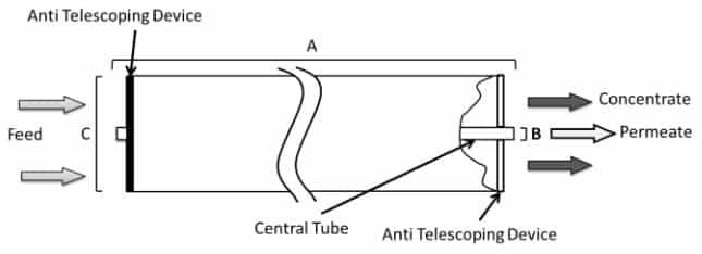
A,B,C Dimensions, inches (cm)
| Model 1 | A | B | C | Boxed Weight lbs (kg) |
|---|---|---|---|---|
| HWS 2521 Models | 21.0(533) | 0.75 (1.90) OD | 2.4(6.1) | 1.3(0.6) |
| HWS 2540 Models | 40.0(101.6) | 0.75 (1.90) OD | 2.4(6.1) | 4(1.8) |
| HWS 4040 Models | 40.01(101.6) | 0.625(1.59) | 3.9(9.9) | 9(4.1) |
| HWS 8040 Models | 40.0(101.6) | 1.125(2.86) | 7.9(20.1) | 29(13.2) |
1 A includes the interconnector.
2 Internal diameter unless specified OD (outside diameter).
3 The element diameter (dimension C) is designed for optimum performance in GE pressure vessels. Other pressure vessel dimension and tolerance may result in excessive bypass and loss of capacity
Table 3: Temperatures
Do not exceed 20 GFD (34LMH) in any circumstances
| Model | Maximum Operating Temperature | Maximum Cleaning Temperature | Maximum Sanitization Temperature |
|---|---|---|---|
| Duratherm HWS RO HR | 122°F (50°C) | 122°F (50°C) | 194°F (90°C) |
| Duratherm HWS RO | 122°F (50°C) | 122°F (50°C) | 194°F (90°C) |
| Duratherm HWS SG | 122°F (50°C) | 122°F (50°C) | 194°F (90°C) |
| Duratherm HWS NF | 122°F (50°C) | 113°F (40°C) | 194°F (90°C) |
| Duratherm HWS UF | 122°F (50°C) | 122°F (50°C) | 194°F (90°C) |
Table 4: Pressures and operating parameters
| Model | Max Operating Pressure 41-122°F (5-50°C |
Typical Applied Pressure | Rec. Element Recovery | Typical Operating Flux |
|---|---|---|---|---|
| Duratherm HWS RO HR | 600psi (4,137kPa) | 225psi(1,551kPa) | <15% | 225psi(1,551kPa) |
| Duratherm HWS RO | 600psi (4,137kPa) | 225psi (1,551kPa) | <15% | 10-18GFD(17-31LMH) |
| Duratherm HWS SG | 600psi (4,137kPa) | 225psi(1,551kPa) | <15% | 10-18GFD(17-31LMH) |
| Duratherm HWS NF | 600psi (4,137kPa) | 110psi(760kPa) | <15% | 10-18GFD(17-31LMH) |
| Duratherm HWS UF | 600psi (4,137kPa) | 80psi (552kPa) | <15% | 10-25GFD (17-40 LMH) |
1 Do not operate at T>50°C (Sanitizing only)
Table 5: Operating and CIP parameters
| Model |
pH range
|
Chlorine tolerance | Feed Water | |||
|---|---|---|---|---|---|---|
| Duratherm HWS RO HR | 4.0-11.0 | 2.0-11.5 | 500 ppm-hours1 | NTU < 1 SDI < 5 |
||
| Duratherm HWS RO | 4.0-11.0 | 2.0-11.5 | 500 ppmhours1 | NTU < 1 SDI < 5 |
||
| Duratherm HWS SG | 2.0-10.0 | 1.0-10.5 | 500 ppmhours1 | NTU < 1 SDI < 5 |
||
| Duratherm HWS NF | 3.0-9.0 | 2.0-10.5 | 500 ppmhours1 | NTU < 1 SDI < 5 |
||
| Duratherm HWS UF | 4.0-11.0 | 2.0-11.5 | 5,000+ ppmhours1 | NTU < 1 SDI < 5 |
||
Dechlorination recommended
HOT WATER SANITIZATION RECOMMENDATIONS
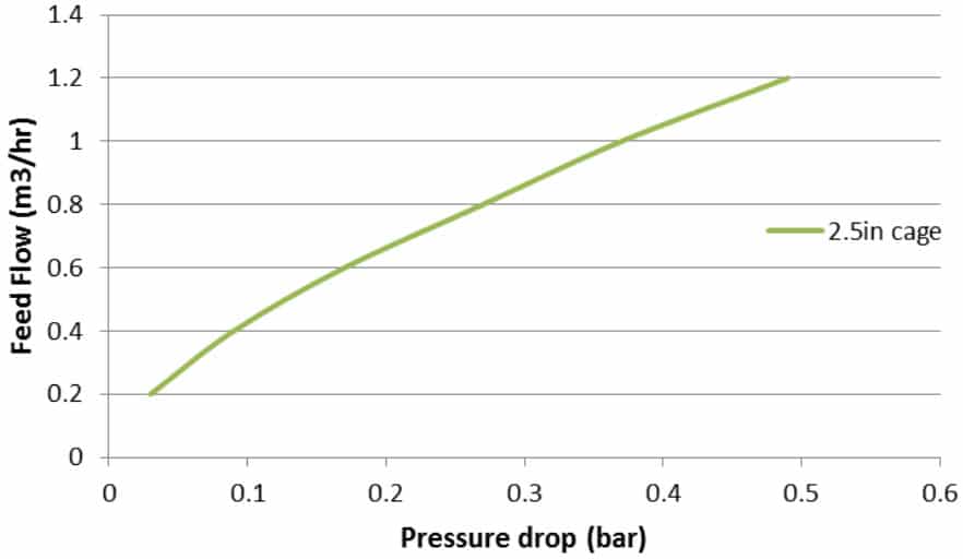
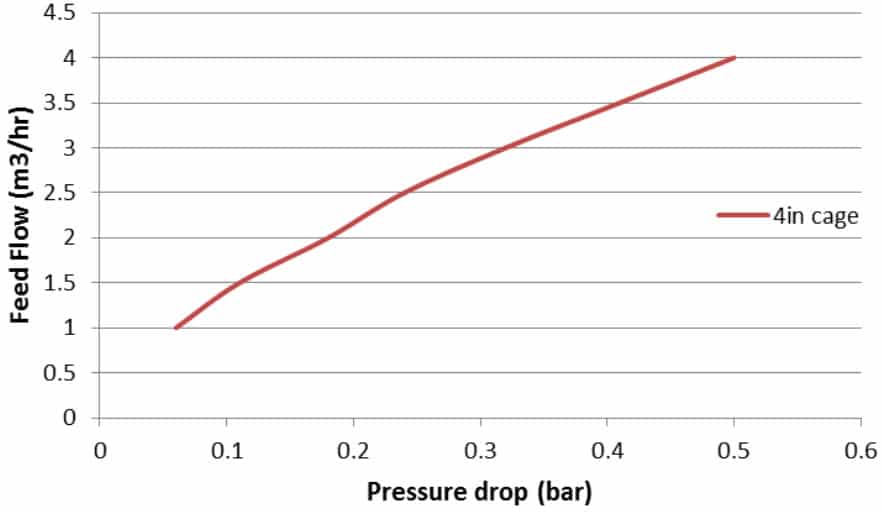
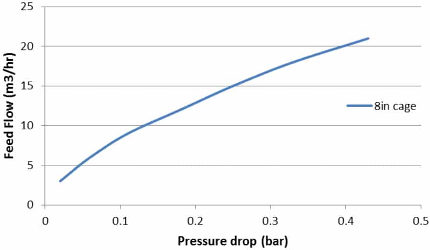
For optimal performance, Duratherm HWS elements should always be cleaned using approved CIP procedures and flushed with fouling free water before the sanitization process. Feed pressure during sanitization should not exceed 40psi (275kPa) and the crossflow should not incur a pressure drop greater than 2psi (14kPa) per element. Heating rate to sanitizing temperature and cool down should not be faster than 5°C (9°F)/minute. Maximum sanitization temperature is 90°C (194°F).
LOSS OF PERMEATE FLOW AFTER REPEATED 90°C (194°F) SANITIZATION CYCLES
It is almost impossible to exactly predict the percentage of permeate flow rate lost from the high temperature sanitations, which among other factors depends on:
- Rate of temperature increase and decrease.
- Presence of other species like organics, ionic and metallic compounds that could locally decrease or increase the temperature at the surface of the membrane.
- Feed flow rate and specifically the heat transfer rate to the membrane surface.
- The thickness and geometry of the feed spacer used.
At optimum conditions measured in controlled environment with deionized water, a loss of flow is observed before the element performance had stabilized after repeated heat treatments (over 90% of this flow reduction occurred during the first heat treatment). This loss of flow represents:
- maximum 25% for Duratherm HWS RO HR
- between 30% and 50% for Duratherm HWS RO, HWS NF and HWS UF
With the loss of permeate flow rate, the salt rejection increases. The rate of cooling and heating was not more than 5°C (41°F) per minute, and the differential pressure drop per element did not exceed 2 psi.
Pilot testing based on the criteria noted above will give the best operating parameters for any specific application.
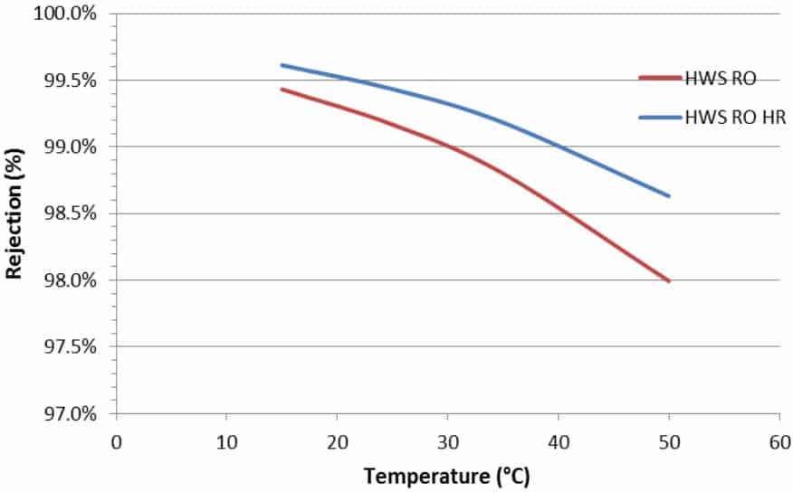
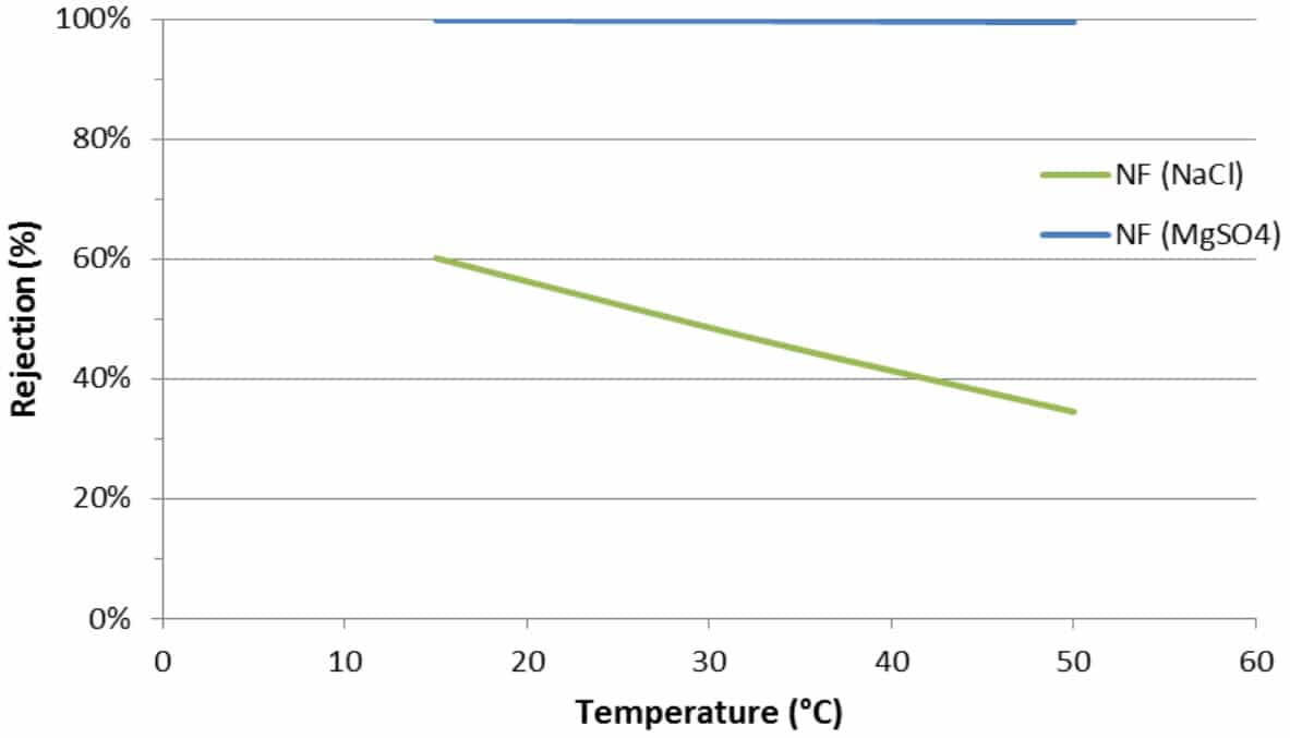
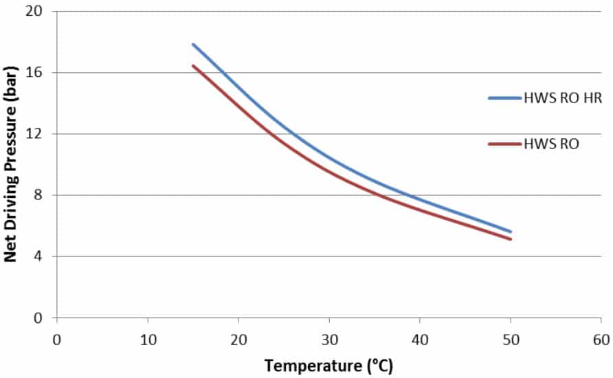
All the graphs below are RO Winflows simulations (Winflows 3.2.1 Database 3.07) which consider a 50% permeate flow loss for the HWS RO and 25% for HWS RO HR.


